Discorz wrote: ↑06 Oct 2022, 10:13
This is great idea; better bring measured GtG data into method rather than vice versa.
You can do it bidirectionally! Measure both by oscilloscope AND pursuit camera, and make sure they match.
It works well when you do it from both ends -- it is verifiable data that verifies each other. If the photograph is identical in blur to the pursuit photograph, then both measurement methods were very likely done correctly.
The great thing is that you can even extract GtG data already from a TestUFO pursuit camera image! You just capture a pursuit camera photo of
https://testufo.com/blurtrail#thickness=-1 simply by mapping the horizontal axis of the lumas along the photo to a graph.
Pursuit-photographed blur edges measurements actually map very accurately to a photodiode oscilloscope of one GtG transition! It's low samples/sec but it is a 1:1 perfect match to an oscilloscope curve (to the error margin of greyscale / camera noise).
It's also further evidence that confirms pursuit camera is effectively WYSIWYG too (during eye tracking), excluding temporal effects (like temporal dithering), which are not animated in a photograph.
Also, the faster motion speed, the more GtG plots per second you can do.
At the moment, 1000 pixels/sec allows roughly a resolution of 1000 GtG/sec in the resulting pursuit camera photograph, if the camera is tracked correctly.
Pursuit photos are not as high resolution as a photodiode oscilloscope, but it uncannily matches the result of a photodiode oscilloscope if you adjust the exposure settings that the blacks & whites do not clip, and if the camera has linear CCD response (most do, at least if you use manual settings / use RAW format).
In theory an app can do this, and with an accurate sync track, with an AI-recognition of the sync track, could probably make it very easy for end users to do in a smartphone app on modern Galaxy/iPhone.
With AI recognition of sync track accuracy (realtime in a pursuit camera app), I imagine a resolution of about 4000-8000 samples/sec can be automatically achieved with no human intervention with mere smartphone pursuit photography with just mere iPhone ~8-10ish and later, and Galaxy ~S15-20ish and later -- with just a single long exposure -- so a smartphone camera can replace a photodiode oscilloscope at low sampling resolution. The horizontal resolution of a smartphone camera image will be the limiting resolution, since you have one “photodiode oscilloscope sample” per horizontal pixel. Assuming you keep the line extremely thin, and horizontal resolution high, the horizontal axis of a horizontal pursuit camera that’s very accurately tracked, is a defacto perfect plot of a photodiode oscilloscope graph!
So that’s pretty neat that the pursuit camera + oscilloscope is in sync! What is needed is a new measurement method that can bring the two together even more closely, and new scoring metrics/formulas that avoids the wholly outdated 10%-90% cutoffs, while respecting noise thresholds. Cameras, understandably, can generate noisy images, so higher cutoffs is still needed. The NEAT thing about a camera image is that you can average multiple pixel rows together (since the vertical axis is duplicate — the line is the same at top edge as bottom edge), so you can get practically 16-bit oscilloscope precision from a single smartphone image!
Because it’s literally ~4000 pixel rows in a modern smartphone camera image — so like ~4000 runs of a photodiode oscilloscope! So you GtG-trace each pixel row of a pursuit camera image, and average all the pixel rows of a pursuit camera image — and BOOM — literally 16-bit oscilloscope precision. (You may need to geometrically/rotation-correct the image data to improve samples/sec accuracy — but this can be done as a pre-step or compensated per-pixel row, based on known image geometry for the photography distance).
Albiet at low samples/sec, a single image is only necessary, because of the sheer megapixels of a camera sensor. How beautiful it is, such math tricks are possible — to pull an uncannily accurate 1000-4000 samples/sec photodiode oscilloscope directly from a SINGLE pursuit camera image.
This is actually worth a science paper sometime (yoo hoo researchers, please let me vet your paper, and add me as a cite. I’m already cited in 25+ papers and inspired over 100+ papers without a cite —
www.blurbusters.com/area51 …)
Obviously, camera photography technique varies, so it has to be a continuously-open shutter for the duration of the photograph, with no ISO variances, to accurately do this. This works when selecting the most unprocessed setting of your specific smartphone camera — latest Galaxy and iPhones are capable of being configured into a pretty unprocessed mode that has a good 1:1 mapping to a photodiode oscilloscope within the dynamic range of the camera sensor, assuming you calibrate/compensate-for the reference blacks & whites. But some niche settings will do weird things to camera sensors.
A smartphone camera being an accurate photodiode oscilloscope is improved by averaging multiple runs — and the multiple runs are already in a single photograph!!! The vertical dimension of the photograph has many pixel rows. This can be averaged/stacked to create a more accurate GtG curve with literaly 16-bit-like Tektronix oscilloscope quality precision! Even if a very low samples/sec (1000 to 8000ish. This is possible because GtG is plotted horizontally across the horizontal axis of a pursuit photo, and a
single blur edge is an exact map to a photodiode oscilloscope! This was also confirmed by the researchers that did the pursuit camera paper.
Discorz wrote: ↑06 Oct 2022, 10:13
If the software simulates the blur accurately we could measure it directly from program.
You can measure it from a good math calculation on an ultra-high-resolution GtG1%-99% heatmap (preferably 256x256 heatmaps, not the puny manufacturer 17x17 heatmaps or the reviewer 5x5 heatmaps).
Discorz wrote: ↑06 Oct 2022, 10:13
I'm afraid by the time any of this gets realized, ultra fast 1kHz+ displays might already become a standard. After that we perhaps won't need it as much.
We still need it even with 1Khz+
A 500 Hz OLED has clearer motion than a 1000 Hz LCD precisely because of GtG speed limitations.
GtG is independent of refresh rate -- GtG can overlap multiple refresh cycles (e.g. 33ms-50ms+ 60Hz LCDs of 1990s, and today's 10ms+ 240Hz VA LCDs in actual reviewer measurements). While average MPRT100% cannot become less than one refresh cycle, GtG can blur far beyond a refresh cycle, that's why we need to get as close as possible to 0ms-GtG.
On LCD, a strobe backlight can hide GtG away from MPRT fully, where GtG is panel-based in the dark cycle, and MPRT is the backlight-driven part. But...
For, OLED GtG of 0.1ms is a big problem for OLED strobing. The GtG:MPRT ratio during BFI can cause color shifts and other artifacts. For example, if GtG is 10% of MPRT on an OLED, then you can have artifacts. 0.1ms GtG versus 1.0ms MPRT is a 10% ratio!
We will still need to measure GtG even in this era.
Discorz wrote: ↑06 Oct 2022, 10:13
Chief Blur Buster wrote: ↑04 Oct 2022, 22:26
And you know, that's why higher resolutions are easier to see motion blur
I haven't considered resolution/ppi stuff at all but now I see at some point that also needs to be taken into account because motion blur is fixed to pixels. As we switch to higher resolution, pixel size usually gets smaller, then higher sensitivity is required to match the former, therefore we get more blur per inch. I guess this should be solvable with something like pixels/inch speed instead of pixels/second.
Inches of blur is unchanged even at higher resolutions -- so more pixels are blurred for the same physical motion speed -- which is why motion blur is instantly more noticeable by humans at higher resolutions than lower resolutions. If the source image was already blurry to begin with (camera blur, low resolution), display motion blur of the same physical inch/sec is harder to see. But as resolutions go higher, you see bigger difference between stationary image and moving image.
That's what we call the Vicious Cycle Effect --
www.blurbusters.com/1000hz-journey#viciouscycle
If you didn't understand the Vicious Cycle Effect before, now you do.
Because the static resolution becomes sharper but motion resolution does not improve, you see a bigger difference between static resolution and motion resolution (for the same sample-and-hold effect aka same refresh rate at same 0ms GtG pixel response)
That's why as soon as we reach 16K virtual reality 180-degrees, where pixels are still individually resolvable, the retina refresh rate starts to rocket to quintuple digits (>10,000 Hz). We've estimated it to roughly 20,000fps at 20,000 Hz for the vanishing point of diminishing curve of returns for the most extreme motion on the most extreme displays. But this may need to be oversampled to 40,000Hz+ if you want to add GPU motion blur effect to eliminate stroboscopics (stationary gaze moving object situation).
For most displays, most humans can't accurately eye-track faster than one screenwidth in about 0.5 seconds (there's another thread about this). We discovered a new rough rule of thumb of retina refresh rate for a display is roughly 2x horizontal resolution, as long as the static pixels are individually resolvable. e.g. stationary versus scrolling starfield of pin-point stars. The stars become ovals instead of dots. Or you do tiny-text readability tests like
www.testufo.com/map -- anything that forces a human to try to tell apart the resolution of a stationary image versus a moving image.
The rule of thumb isn’t perfect, but it’s an amazing estimate that has a smaller error margin than expected — it is a function of the maximum fastest eye tracking speed from left edge to right edge of display, and enough time to stare at a moving object to identify if it’s sharp or blurry. That was deemed to be approximately 0.5 seconds. Some people can track faster, and others slower, but it also takes time to identify an object too — if moving object appears and disappears too fast (from one edge to other edge of screen), you don’t have enough time to pay attention to the moving object in order to notice whether it’s sharp or blurry.
So in other words: A great rough estimate of a display’s retina refresh rate is approximately twice the resolution along the vector of the moving object (e.g. the display’s horizontal resolution for a horizontally moving object).
If the human eye’s angular resolution along the dimension is lower than the physical resolution (e.g. display excess spatial resolution far beyond retina resolution), then that applies instead of the actual physical resolution.
When done, retina refresh rate becomes incredibly high for a sample-and-hold non-strobed non-PWM non-flicker display:
As an example:
Rough ballparks, but error margin is almost certainly far less than one order of magnitude from these estimates:
- For a smartphone display at arms length, the retina refresh rate could be about 500-1000
- For a 1080p 24" display at arms length, the retina refresh rate could be about 2000-4000
- For a 4K 27" display at arms length, the retina refresh rate could be about 4000-8000
- For a 180+ degree VR headset with 16K resolution, the retina refresh rate could be about 20000-40000
During eye-tracking maximally-detailed maximally-fast motion (for motion blur), for an extreme cherry-picked test.
Obviously “retina resolution” and “retina refresh rate” is a great oversimplification, but Blur Busters like to toe the “Popular Science” line, where I use terminology that’s reasonably easy for most educated people to understand — not just researchers.
Once the pixels of a display becomes tinier than human angular resolving resolution at the (real/virtual) viewing distance, you've hit "retina resolution" (Apple term, I like using user-friendly terms on these forums). Now you've maximized the retina refresh rate of the display. So if you stretch a 16K VR display to 180 degrees, the pixels become big and even resolvable (barely), and twice that is 32000Hz. So that's a crazy 32000fps 32000Hz. I often quote 20000fps 20000Hz, but that is only lower-bound estimate for an extreme-wide-FOV retina-angular-resolution display.
1000fps 1000Hz is just a boilerplate as the most economically feasible "almost retina refresh rate" for a 24" 1080p OLED display. But once we go to 4K or 8K, watch out, it really starts to feel non-retina Hz and you need even more frame rate and Hz to begin to see panning images as clear as stationary images without needing strobing.
Obviously, once you strobe (like a CRT), motion blur disappears, but stroboscopics gets worse whenever eyetracking is not in sync with the moving images. This can be fixed in a VR headset with eye-tracking-compensated GPU-motion-blur effect, that dynamically motionblurs the delta between eye gaze motion vector and the moving-object motion vector. So that stationary-gaze stationary-object is tack-sharp, and tracking-gaze moving-object is tack-sharp, but all divergences (stationary-gaze moving-object, as well as moving-gaze stationary-object) no longer has stroboscopics because the eye tracker automatically told the GPU to add artifical motion blur to hide stroboscopics during tracking-divergence situations. I already cover this topic at the bottom of
The Stroboscopic Effect of Finite Frame Rates, a section of
www.blurbusters.com/area51
Discorz wrote: ↑06 Oct 2022, 10:13
Chief Blur Buster wrote: ↑04 Oct 2022, 22:26
This does not translate well / confuses a bit because it's an interpretation that I don't use -- the blur doesn't stop in a horizontal line in between -- it just gaps. So it's not cumilative
I can confirm the strobed chart is accurate, at least for this case.
It is accurate if you're not trying to sync quantitative and qualitative (aka what the human eye saw).
But, it just confuses my mind more than it puts at ease, so I prefer a totally different visualization.
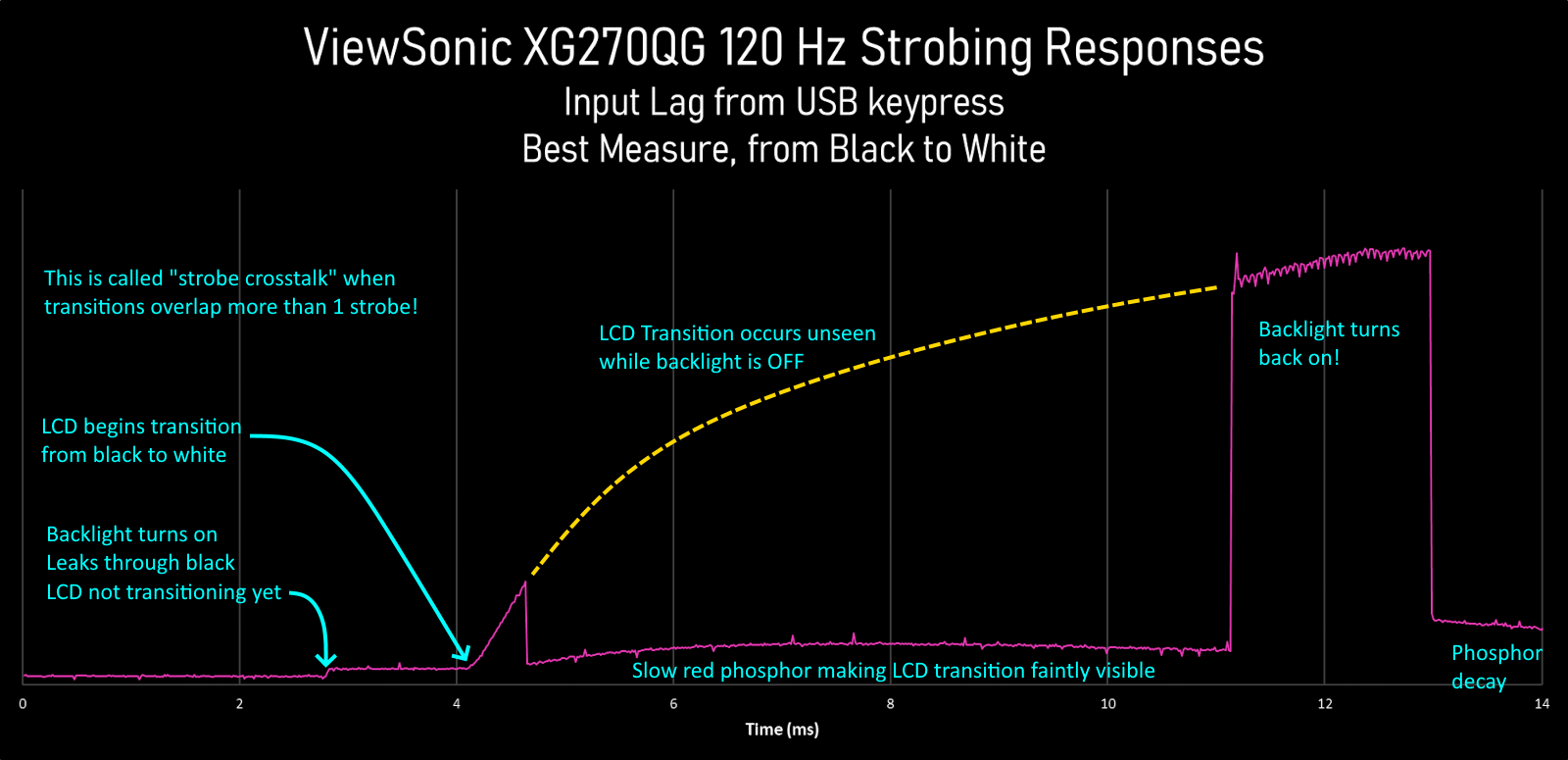
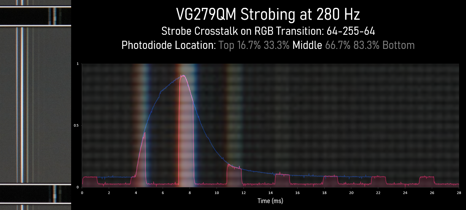
Also, complicating matters, we have complex situations of strobe crosstalk concurrently combined with KSF phosphor decay:
Discorz wrote: ↑06 Oct 2022, 10:13
The reason it looks the way it does is because given transition is sent and held for a longer period to make sure it fully completes, basically treated the same way as classic GtG measuring.
The GtG transition doesn't pause -- it continues unseen by eyes.
That being said, deep thought is required for a user-friendly visualization that doesn't confuse end-users nor confuse me; because everybody thinks differently. Some people think "geometically" when doing some math formulas (they don't read out the numbers in their mind) while other people think more algebraically. It's a major reason why some people have a tough time with algebra-based professors while having much easier time with geometry-based professors -- there are MANY ways to teach the same kind of mathematics to the same person. It might be a math-equivalent of dyslexia. I don't know.
Regardless, that one earlier graph you posted is totally confusing to my mind -- and that must be solved with a more universal visualization that is less confusing to a wider audience.
But the newer graph, is perfect to my mind:
That one is easy to understand -- the blue line is what the panel is doing independently of the backlight -- and the purple line is what the human eye (and pursuit camera) saw. And correlates perfectly to the intensities of the duplicate images afterwards. It even correlates
perfectly to the GtG-plot recorded from a pursuit image of
www.testufo.com/blurtrail (single-pixel thick for MPRT/crosstalk analysis) or
www.testufo.com/blurtrail#thickness=16 (thickness=ppf for double-GtG curve)
www.testufo.com/blurtrail#thickness=-1 (single edge for single-GtG curve) using the technique I described earlier -- In the photo, the first line is strong, the next duplicate line is fainter -- and so on -- and and the final line is faintest. And within each duplicate is a soft blur gradient that matches the shape of the spikes of that graph! And when plotted to a graph, the graph matches that image. That's why pursuit images are in sync with such complex graphs!
Discorz wrote: ↑06 Oct 2022, 10:13
Also there needs to be some proof of differing transitions with similar/same CDs matching similar/same perceived blur as we'd want to directly compare one to another (e.g. sample and hold 144Hz OLED matching 240Hz LCD...) or even strobing on vs off situations. Not to mention interpreting over/under/shoot. Obviously two will never look identical but according to CD they should at least
feel. This is where we run into a problem.
That's part of a project I am currently working on.
One major solution is obsoleting the old VESA GtG 10-90% thresholds, as even a $25 Arduino photodiode tester (with a gain adjustment) can measure GtG 1%-99% pretty accurately for the entire heatmap of a 300-400nit, even the darks.
VESA designed the standard using an oscilloscope directly connected to a photodiode without an opamp.
But today, the maker culture builds an opamp straight into an Arduino photodiode oscilloscope to amplify the sub-GtG10% and post-GtG90%.
Other techniques such as repeating the GtG curve read and averaging the GtG curves removes a lot of noise too, to allow a $25 tester to surpass accuracy of a single-pass of a $1000 Tektronix oscilloscope. It's year 2022. This ain't the 1990s, VESA.
The VESA GtG and MPRT measurements are so outdated I now considered "compromised" and violates honesty with the people complaining about it. A better measurement method requires consultation with a wide number of reviewers (something I will begin doing soon too). They came up with a new motion blur measurement standard completely different from GtG and MPRT, without also concurrently fixing GtG and MPRT 10%-90% thresholds. Now, they've started major confusion.
I'm dissapointed that VESA did not consult Blur Busters first for comment -- nor even cited the pursuit camera sync track which is also useful even for motorized cameras. Though pixel-shifted images from a high speed camera (>1000fps) can also be used to create pursuit camera images. But that's not even necessary -- you just need a single pixel photodiode and oscilloscope it all -- and generate virtual pursuit camera images. But we will have an answer (articles about this) in the coming months as we begin to re-activate the main page of Blur Busters news.
Keep tuned for an announcement. I can't say much yet, but I can confirm we're developing new standards. But the thread really touches upon some current projects that I am doing internally.
Discorz wrote: ↑06 Oct 2022, 10:13
It definitely needs to be done right and be fully flexible at the same time. There are so many things to take into consideration. Phosphor decay also. If everything turns out right stroboscopic effect simulation should be just one click toggle.
It really is a dream.
And we're going to make this dream happen this decade.
A universal software-based display simulator is already in the works, but it will need a long incubation period.
I have lots of raster beam racing knowledge (see
Tearline Jedi) and understand exactly how to make the same codebase simulate almost any single-pass scanout display (CRT/LCD/OLED) simply by changing variables. And with some further iteration, multipass-refresh algorithms (colorwheel simulation, DLP/plasma temporal dithering simulation).
It only requires less than approximately 10,000 lines of code -- it's not that big for a display simulator kernel that runs off simple variables. It's just complicated to understand. The problem is understanding the concepts -- most researchers don't concurrently understand enough simultaneously (a CRT researcher might not understand LCD+strobing behaviors), but I understand refreshing behavior of so many displays simultaneously.
A professional may understand spatials excellently (e.g. MAME HLSL), but they don't understand temporals.
Some people have photogenic memory. Others math brillance. I've got the temporal brillance: I can simulate displays in my mind. Adjust a variable and I can usually picture the artifacts that outputs from it.
People who know me know that I've got a very good temporal mind -- I can simulate displays in my mind! That's how I invented
www.testufo.com/ghosting and
www.testufo.com/eyetracking ... I saw the artifacts in my head before I wrote those tests. I happen to be an occasional computer programmer too. That makes me ideally situated to convert my brain-based display simulator to a computer program. It's easy.
The main chicken and egg is I need to be paid (funding) for the time, because I can't afford to do too much things for free -- I already do (e.g. TestUFO) -- but perhaps a Patreon could help light up certain projects like these, although I don't know what audience would be willing to pay. I don't have the catchet of a LinusTechTips or VSauce or MrBeast, to pull in even a single thousand dollars worth of Patreon per month -- so I rely on services at
services.blurbusters.com (working with manufacturers) as well as banner ads -- to pay the bills as well as pay my subcontractors and everything.
Nontheless, a universal display simulator codebase can easily be created in 2023 if funding is available... A single $5000-$10000 donor would instantly pay for my time and get it done in a couple months or so, and open-source it under Apache-2.0 or MIT on github.
- Useful for end users as education (super Blurinator equivalent)
- Useful for reviewers when importing photodiode data to create virtual pursuit camera images
- Useful for manufacturers to prototype future displays.
- Useful for non-realtime (e.g. simulated pursuit images, or slow-motion simulation of a display)
- Useful for real-time
.....CRT electron beam simulator for emulators
.....Add G-SYNC native quality overdrive to generic VESA Adaptive Sync displays (using GPU shader to do the VRR overdrive processing)
.....Etc
GPU shaders are so astoundingly powerful, that this can be done with less than 5-10% of GPU overhead now, even at 240Hz.
Initially it'd start with simulating a display utilizing single-pass rolling scanout (CRT, LCD, OLED), with an optional global or rolling strobe. It would successfully do accurate virtual pursuits of all 3 major display technologies (of any subtype like TN, VA, IPS), with various kinds of adjustable variables like phosphor decay, nits, Hz, GtG formula or recorded curve data (from photodiode oscillscope / Arduino) etc. Hell, the Arduino device could be directly connected to the app! Allowing users to do DIY custom overdrive, as one example.
That is pretty simple. Easier design of superior overdrive would be the first spinoff benefit of a display simulator.
Then it'd iterate to include more complex things like HDR features, like VRR features, like VRR dynamic overdrive, like local dimming and its blooming artifacts, like like multi-pass refreshes (e.g. DLP, plasma) with subrefresh temporals, and other display-simulator features. Plug-in modules or plug-in shaders could add displays. You could even test new subrefresh dithering algorithms in a GPU shader before implementing it to a FPGA, or test new LCD overdrive algorithms before programming a scaler/TCON.
But initially -- for the basic display simulator kernel Version 1 -- It's not a complex program, just time-consuming to test and compare with displays I have to purchase to validate, or the time spent recruiting volunteers to compare to displays, etc -- stuff that takes away from paid time. For now, I have to stick to paid projects.
It is harder to do other things such as language porting or programming a Windows Indirect Display Driver (e.g. to do things like virtualize a 60Hz Windows Display which is then used to CRT electron-beam-simulate onto a future 1000Hz OLED) -- so that Windows thinks it's connected to a 60Hz CRT when the real display is a 1000Hz OLED (and the Universal Display Simulator is embedded in a third party Windows Indirect Display Driver)! Simulate the retro display of your dream, assuming you have enough Hz to simulate the retro display at fine enough temporal granularity. In theory, longer-term, I'd even be able to add beamracing support, so that software-simulated tearing can happen, or hooks can be added for lagless CRT scanout (via frameslice beam racing algorithm), e.g. an API called from an emulator to deliver a frameslice to be scanned out.
But the Display Simulator Engine is easy for me to write -- under 10,000 lines for Version 1 of CRT/LCD/OLED simulation engine -- just very complex for anybody other than me. You can see how tiny Blurinator is -- it's just a few lines of source code! But it only simulates LCD and only global refresh -- it does not simulate scanout (so it doesn't show top/center/bottom crosstalk differences). I also want to see it in a different language such as C# which is much more easily portable to C++ (e.g. emulators) and JavaScript (e.g. TestUFO simulators), and it so happens that my favorite casual development language is.... C#
The bottom line is the kernel of a relatively expandable & universal display simulator is shockingly rudimentary -- partially because displays are just electronic visualizations of an unchanged display signal -- a raster display signal is mostly unchanged in topography (vertical & horizontal sync and porches) and thus most displays have processed the signal in surprisingly minimal ways, despite the advancedness of current modern VRR FALD displays.
On the other hand, manufacturers might find a display simulator useful to prototype future displays.
TL;DR: The *start* of a Blur Busters Universal Display Simulator engine isn't a particularly hard project for me -- just needs to be funded by either a donation or a client. Or a BountySource prize, perhaps.


