Math Formulas for phosphor decay & LCD GtG [provided!]

Advanced display talk, display hackers, advanced game programmers, scientists, display researchers, display manufacturers, vision researchers & Advanced Display Articles on Blur Busters. The masters on Blur Busters.
ScepticMatt
Posts: 37
Joined: 16 Feb 2014, 14:42

Math Formulas for phosphor decay & LCD GtG [provided!]

Post by ScepticMatt » 06 Mar 2014, 16:15

Chief Blur Buster wrote:-- I am thinking of eventually writing an online TestUFO motion blur modelling program (TestUFO Motion Blur Modeller/Emulator/Predictor). Much like the custom motion blur modeller in PixPerAn, but modernized for the 21st century reality of faster LCDs and strobe-backlights.
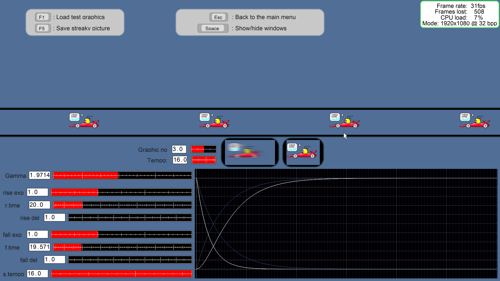
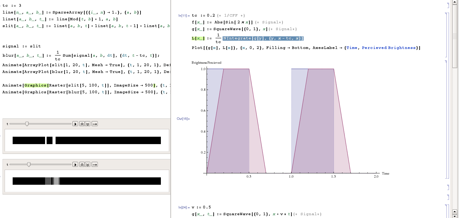
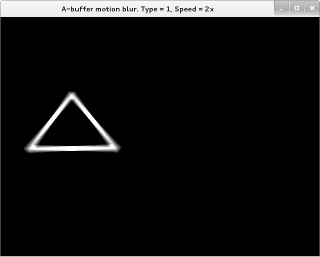
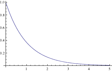
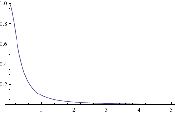
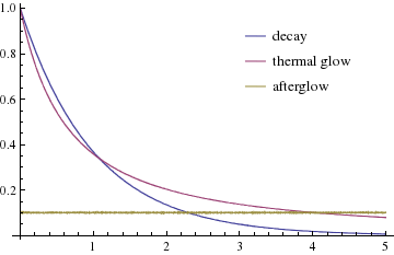
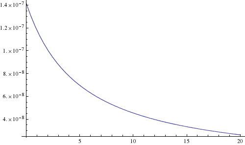
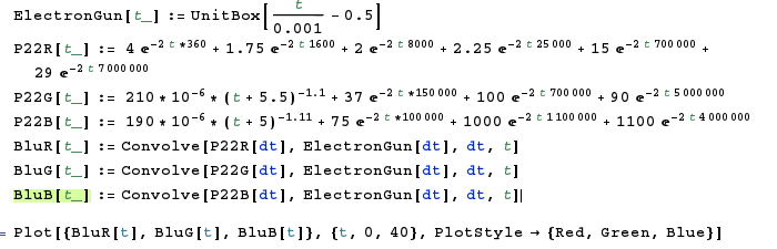
-- Basically, one can tweak sliders, and see algorithmically simulated motion blur that matches what you preceive (or photographed by tracking pursuit camera) and contains some easy-select presets of known motion blur variables (e.g. typical 1-2ms 60Hz, typical 1-2ms 120Hz, CRT, LightBoost 10%, LightBoost 100%, Blur Busters Strobe Utility 0.5ms, Blur Busters Strobe Utility 2.0ms, Blur Busters Strobe Utility 4.0ms, etc.). Basically a motion blur simulator that factors in persistence/duty cycle. I know how to create a very accurate one, although I might need some help with the formulas (e.g. GtG often has pixel ripple, and I'm not sure how to simlate that -- I might need to ask for some formulas). CRT phosphor decay would also even be easy to emulate in this same application if I just get a formula that approximates phosphor -- it's simply a sudden-ramp-and-slow-decay (phosphor trail) rather than a squarewave (linear motion blur), and simply run different blurring formulas for R/G/B (G has the slowest decay, so that's why there's green trailing effect). So the same modelling program can easily simulate motion blur of sample and hold LCD (of varying GtG response speed for a specific pair of colors in both directions), simulate motion blur of short-to-long persistence CRT, simulate motion blur of strobe backlight (of varying strobe lengths). Factoring in persistence (and for each channel of color separately) automatically makes the application compatible with accurately modelling of motion blur of persistence of CRT, persistence of LCD, persistence of strobe backlights, and persistence of many other display technologies. If one add high-frequency subpixel effects, I can also accurately model motion blur of plasma/DLP (including the "noise" in motion blur too!) -- all one would need is the error-diffusion math formulas for each pixel color, and then of a sudden one would be easily emulating the plasma banding effects in software!! It's really a simple matter of emulating per-pixel motion blur based on the PWM duty cycle of each pixel individually, where each of the pixels individually motion blur for each different lengths, and patterns in error diffusion interact with each other, creating artifacts like the noise/band artifacts found in plasma/DLP motion blur. But I wouldn't bother per-pixel for the first version of the TestUFO Motion Blur Modeller if I created one. I'd simply focus on simple squarewave persistence first (easiest to model), followed by ability to manually enter an algebriac formula (or presets for CRT fast phosphor, CRT slow phosphor, 1ms LCD, 2ms LCD, for 8ms IPS -- if formulas approximating those can be come up, e.g. logarithmic, gaussian, sine, squarewave, etc), perhaps three different formulas for R/G/B (since the three CRT phosphor primary colors have different decay behaviors), and viola -- one can accurate emulate tracking-based motion blur (visual-based and camera-based) of virtually any possible single-strobe display like CRT/LCD/OLED/etc (displays that didn't modulate pixels multiple times indepedently of each other, like plasma/DLP -- that'd require per-pixel modelling). Ideally something HTML5 based, so I could integrate it as part of TestUFO; it may be a project I may do later in 2014, though I'm also open to collaborative efforts (in Javascript/C#/Java/C++).
-- This app wouldn't be factoring in things like judder/stutter/temporal aliasing effects/low framerates on strobed, but could theoretically be easily updated to also include blurring/doubleimage effects caused by those effects.
Nice. I actually experimented with this myself, but far less sophisticated (so it seems)

How are you handling the characteristics of the HVS/display the simulation is running on? Are you assuming a 'perfect display' and are you considering slow-mo / increased size to bring frequencies below nyquist or are you including the characteristics in your models (with limitations)?

User avatar
Chief Blur Buster
Site Admin
Posts: 11653
Joined: 05 Dec 2013, 15:44
Location: Toronto / Hamilton, Ontario, Canada
Contact:

Re: Temporal anti-aliasing for computer generated graphics

Post by Chief Blur Buster » 06 Mar 2014, 16:48

Thanks, lots of good information -- some of it slightly beyond the scope of my knowledge, even!
I'm focussing mainly on the "simpler" stuff, like visual behavior of continuous motion (without temporal anti aliasing).
ScepticMatt wrote:Nice. I actually experimented with this myself, but far less sophisticated (so it seems)
How are you handling the characteristics of the HVS/display the simulation is running on? Are you assuming a 'perfect display' and are you considering slow-mo / increased size to bring frequencies below nyquist or are you including the characteristics in your models (with limitations)?
Display would not matter for this simulation because it is a static image that emulates what was perceived when tracking. I presume you're familiar with the static image of simulated motion blur in PixPerAn?

The motion blur simulator I'm proposing would be a static image with algorithmically calculated blur, so it will be display-independent for the static portion of the motion blur emulator. The goal of the motion blur emulator is to aims to look like a snapshot of was perceived (eye accurately tracking motion), and would look very similar to pursuit camera photograph, except that the image is algorithmically created rather than being a real photograph. That's the same case as for the PixPerAn motion blur simulator mode (static image with algorithmic blur) -- that's the F6 "Streaky Pictures" test, screenshotted below:

Image

As you can see, this is hopelessly outdated, for a 2001 program, the "rise time" / "fall time" isn't configurable below 4ms, and today we've got LCDs faster than this streaaky picures test (look at the left image of two, located right above the graph -- that's the static image motion blur simulator). What I am thinking is creating an online TestUFO equivalent that allows you to select a preset (or enter an algebraic formula) that will accurately emulate all single-strobe-cycle low persistence displays including CRT, strobed LCD, OLED, and more. All of this is pretty simple, and can be very accurately modelled for continuous consistent motion (when assuming judder is simply motion blur). The curves can even take account for GtG overshoot/ripple so I should easily be able to simulate RTC overshoots (and create algorithmically generated static images similiar to the photographs at LCD Overdrive Artifacts).

Eye-tracking (or camera-tracking) essentially simply "plots" the response curve (any photon outout of a pixel versus time) along the vector of motion, so persistence/blur/decay/overshoot effects are easy to calculate/predict in my head without thinking about the math. Although I don't do number math in my head when I calculate predicted motion blur -- my head just simply figures out motion blur. (Note -- I'm talking about constant/continuous framerate=refreshrate motion during accurate tracking; at motionspeeds where saccades are excluded as an error factor, start/stop effects are ignored, and when temporal aliasing is nonissue or negligible). My head imagines predicted motion blur similiar to how other people figures out/predicts geometry and distances just by "thinking" -- and I find I've been pretty accurate in my motion predictions. But I can realize, that I can simply run the curve for for each pixel of a bitmap image (simple matrix math, treating each pixel as a floating point number) then generate an averaged resulting image -- which will end up accurately resembles what you saw. CRT/LCD/OLED/strobing can modelable accurately, excluding per-pixel behaviors (e.g. DLP dithering, plasma subfields, LCD inversion, dithering, FRC, etc) unless I also include per-pixel behaviors which is certainly feasible but far more complicated. I just need to gather the math formulas that creates a curve that accurately resembles an LCD transition, or phosphor decay, etc.

What is needed is scientific proofs that back up some of my observations of the new tech -- and creating a proper modern motion blur simulator (that properly takes into account of persistence/light modulation) will be helpful/useful for motion blur study/research.

My intent was to do it in PixPerAn style manner, to allow you to display static images corresponding to what is perceived by tracking eye (or what is photographed by tracking camera). And secondarily, also to be able to calibrate the static image to match what you're currently perceiving in the moving object on the current display.

-- However, a real moving motion blur emulation (e.g. simulating CRT phosphor decay on LCD) would be distorted by the current display it itself is running on. You cannot accurately emulate a lower-persistence display on the current display you are running on, but you can study the effects in slow motion, as you've suggested. This would be a very simple further addition to the app.

I'm not sure when I would do this, but it would be later in 2014 (maybe 2015). I am also open to collaborations with others (e.g. developing concurrently with you) as long as it's done in a manner that's compatible / portable to website (e.g. TestUFO)
Head of Blur Busters - BlurBusters.com | TestUFO.com | Follow @BlurBusters on Twitter

Image
Forum Rules wrote:  1. Rule #1: Be Nice. This is published forum rule #1. Even To Newbies & People You Disagree With!
  2. Please report rule violations If you see a post that violates forum rules, then report the post.
  3. ALWAYS respect indie testers here. See how indies are bootstrapping Blur Busters research!

ScepticMatt
Posts: 37
Joined: 16 Feb 2014, 14:42

Re: Temporal anti-aliasing for computer generated graphics

Post by ScepticMatt » 06 Mar 2014, 18:04

I see, cool.
Here is what i did so far:
I simulated persistence in Mathematica, and then created an animation for various input signal (discrete blur only)
Image
then I created an openGL applet, where I can simulate motion blur using the accumulation buffer
(in essence 10x+ temporal supersampling, here I used 10x)
I could adjust weights to simulate phosphor decay, and vary positions to simulate eye movements.
Image
The image above assumes eye-tracking, so at low speeds the images stay sharp but still prevent strobing from rotations
(to be precise the eye can rotate 'a little' around the visual axis, but it's rare)
the timings aren't quite right, and I could use better downsampling than a box filter (see the last pdf in the OP)

The pixel images in the op are manually created in photoshop. I'm not sure that was the best idea :)

User avatar
Chief Blur Buster
Site Admin
Posts: 11653
Joined: 05 Dec 2013, 15:44
Location: Toronto / Hamilton, Ontario, Canada
Contact:

Re: Temporal anti-aliasing for computer generated graphics

Post by Chief Blur Buster » 06 Mar 2014, 19:04

Would you be able to do me a HUGE favour? Can you find any math formulas in any science papers that can create curves similar to:
- Phosphor decay of CRT phosphor, of various decay ratings
- Phosphor decay, for each individual phosphor color
- LCD GtG, symmetric, asymmetric, and various levels of overdrive, of various GtG ratings
- Phosphor decay of CCFL, preferably for each R/G/B
- Phosphor decay of white LED (insignificant ~0.1ms or so, but nice to have for extra accuracy)

Graph axis would be:
Y = light
X = time

A simple decay formula is simply Y = 1/X
More complex formulae can also be inverse exponential or logarithmic, or nonlinear, or even multiple-order effects such as ripples (overdrive bounce). If I could collect formulas, I would be able to co-relate it with photodiode oscilloscope graphs for accuracy of formula match, and have sub variables such as T for average pixel GtG transition time (to say, 90% completeness or threshold). For strobing and for PWM, LCD continues its response characteristic even in the dark periods, so all I simply need to do is chop the graph (cliff the curve to zero at intervals, or dip gradually, if for slow CCFL decay. Yes, I would be able to simulate the blue/yellow tinting in cheap fluorescent phosphor decay if I have the curve formula for each color)

Most formulas are so simple i just can enter it into Google Graphing, and be done with it, or use any of the host of graphing calculators to create the curve. Mathematica is good, but overkill for such a simple graphing task targeted at approximating the common display behaviours at least at the global level.

Once I have this formulae, I can very accurately plot the light emission variance Y while smearing a bitmap along the motion vector (X representing time) thusly creating the resulting combined perceived motion blur/ghost/artifact effect. Doing it per pixel granularity is good enough for my needs. Could do it sub pixel, for even better accuracy, but initially will just integrate into a floating point matrix, one floating pint value per pixel, adding up all Y values along X axis at 1 pixel steps along motion vector. Then simply divide all floating point pixels by number of values added up, and viola....uncannily accurate simulated motion artifact! Since subsequent refresh cycles on exact pixel steps have the exact same pixel behaviour (barring response asymmetry in different areas of a panel), I keep repeating the cycles concurrently for a series of refreshes, including GTG that bleeds between refreshes, essentially stacking the refreshes repeatedly over multiple cycles, as I continue to smear the bitmap, I will even be able to precisely reproduce things like double image effects such as CRT 30fps@60Hz (or strobe crosstalk, etc' at least for a given portion of the screen). Motion blur, squarewave strobe, gaussian/sine wave strobe, overdrive, ghosting, coronas, phosphor decay, CCFL PWM, LED PWM, multiple image effects, crosstalk, etc, would be accurately simulated in my program, for consistent motion situations. Accuracy is limited only by the accuracy of the formulas. All in one program since I view motion blur as a simple plot of light emission along time (the motion vector) which is a beautiful, simple, total catch all for all the above! I am simply missing math formulas. In situations of lack of formulas, one can capture a photodiode oscilloscope graph of common GtG color transitions, and run a curve fitting algorithm to come up with an algebraic equation that matches (e.g. To 99% accuracy).

I am totally surprised not many people treats motion artifacts as a simple, single light emission curve against time. It is a catch all for all global motion artifacts described above. It's apparently that simple.

For consistent motion even on non-integer steps, including diagonal motion, the temporal aliasing error is always actually less than one pixel's diagonal (as long as the non integer steps are consistent) and can be considered insignificant for the purposes of reproducing the macro motion artifacts. Future versions of the program or more advanced versions could then expand to include such effects, since it is useful when hold-type blur falls to levels low enough to make the temporal aliasing issue appear. More statistically significant are mouse microstutters. I even think we need 4000Hz mice already, IMHO - or asynchronous 1000Hz mice that can be polled between intervals - to reduce the mouse temporal aliasing effects which is multiple pixels, during a fast "flick 180" in FPS games (4000 pixel per second panning being brought down to single pixel accuracy when aliasing against refresh rate.). 4000Hz mice would vastly reduce the known "lightboost VSYNC OFF jitteriness" due to this. Or I wonder if mice vendors have figured out how to do asynchronous poll (e.g. Mouse camera sensor reads at arbitrary intervals that aren't divisible by milliseconds)
Head of Blur Busters - BlurBusters.com | TestUFO.com | Follow @BlurBusters on Twitter

Image
Forum Rules wrote:  1. Rule #1: Be Nice. This is published forum rule #1. Even To Newbies & People You Disagree With!
  2. Please report rule violations If you see a post that violates forum rules, then report the post.
  3. ALWAYS respect indie testers here. See how indies are bootstrapping Blur Busters research!

ScepticMatt
Posts: 37
Joined: 16 Feb 2014, 14:42

Re: Temporal anti-aliasing for computer generated graphics

Post by ScepticMatt » 06 Mar 2014, 19:32

Work in Progress!
Chief Blur Buster wrote:Would you be able to do me a HUGE favour? Can you find any math formulas in any science papers that can create curves similar to:
- Phosphor decay of CRT phosphor, of various decay ratings
- Phosphor decay, for each individual phosphor color

- LCD GtG, symmetric, asymmetric, and various levels of overdrive, of various GtG ratings
- Phosphor decay of CCFL, preferably for each R/G/B
- Phosphor decay of white LED (insignificant ~0.1ms or so, but nice to have for extra accuracy)
sure. A quick search result gives me the phosphor handbook 2nd edition a 1056 page book about all things phosphor. (including quantum mechanics models, CRT phosphors etc.)
http://f3.tiera.ru/3/Chemistry/Inorgani ... 56s%29.pdf

A quick look gives the simple decay curves (page 108):
I(t) = I0 * exp(-t/Tau) or I(t) = I0 (a/(a + t^n))
Image
Image
It goes into detail after that, still reading.

User avatar
Chief Blur Buster
Site Admin
Posts: 11653
Joined: 05 Dec 2013, 15:44
Location: Toronto / Hamilton, Ontario, Canada
Contact:

Re: Temporal anti-aliasing for computer generated graphics

Post by Chief Blur Buster » 06 Mar 2014, 21:55

Wow, that's a goldmine. I wonder what curve fits a Sony GDM-W900 very well, as well as some popular gaming CRTs. Obviously, I'd need values for each color component, in order to accurately calculate the color of the phosphor ghosting (which is typically greenish).
Head of Blur Busters - BlurBusters.com | TestUFO.com | Follow @BlurBusters on Twitter

Image
Forum Rules wrote:  1. Rule #1: Be Nice. This is published forum rule #1. Even To Newbies & People You Disagree With!
  2. Please report rule violations If you see a post that violates forum rules, then report the post.
  3. ALWAYS respect indie testers here. See how indies are bootstrapping Blur Busters research!

ScepticMatt
Posts: 37
Joined: 16 Feb 2014, 14:42

Seeking Math Formulas for phosphor decay & LCD GtG

Post by ScepticMatt » 06 Mar 2014, 23:18

Big book on phosphor, introduction:
http://f3.tiera.ru/3/Chemistry/Inorgani ... 56s%29.pdf

2.7 transient character of luminescence (p 83.)
persistence: luminescence after-glow (phosphorescence), thermally stimulated emission (thermal glow), photo (infrared)-stimulated emission, and photoquenching

Phosphorescence: I(t) = I0 * exp(-t/Tau) “exponential decay”, fast phosphors
Thermal glow: I(t) = I0 / (1 + y t)^n , n=0.5...2 “inverse power law”, medium phosphors
“Afterglow”: the rest, long duration, dependent on temperature and ratiation
multiple exponentials, powers for more accurate results

Image

this book discusses CRT phosphors and plots some decay curves after p583

More info:
Lost of decay curves with grid to read values
http://dspace.mit.edu/bitstream/handle/ ... 706923.pdf

High order model for PB22 (R/G/B) p6
http://www.cl.cam.ac.uk/~mgk25/ieee02-optical.pdf

NASA phosphore measurements:
http://www.nasa.gov/centers/dryden/pdf/ ... _H-609.pdf

Phosphore measurements + model fitting:
https://tspace.library.utoronto.ca/bits ... Q28777.pdf (afterglow model)
http://www.stanfordcomputeroptics.com/d ... osphor.pdf
http://www3.alcatel-lucent.com/bstj/vol ... -1-181.pdf
http://www.cugb.edu.cn/upload/20600/pap ... 194141.pdf

Lists of phosphor types with glow durations (not research):
http://en.wikipedia.org/wiki/Phosphor
http://www.bunkerofdoom.com/tubes/crt/c ... search.pdf

spacediver
Posts: 505
Joined: 18 Dec 2013, 23:51

Re: Seeking Math Formulas for phosphor decay & LCD GtG

Post by spacediver » 06 Mar 2014, 23:41

great thread, looking forward to reading it thoroughly when I have time over the wknd. One thing I have found is that it is extremely difficult to find solid data on the temporal decay function of phosphors. Props to you ScepticMatt for digging up so much quality info.

As for modeling the decay function using a psychophysical approach as a few of you here have starting doing, see my post here on avsforums.

http://www.avsforum.com/t/1490744/stand ... t_23890492

ScepticMatt
Posts: 37
Joined: 16 Feb 2014, 14:42

Re: Temporal anti-aliasing for computer generated graphics

Post by ScepticMatt » 06 Mar 2014, 23:48

Chief Blur Buster wrote:Wow, that's a goldmine. I wonder what curve fits a Sony GDM-W900 very well.
Sonys broadcast model uses P22 phosphors, and it's also used in consumer models, so yours might also have P22s. I've posted a VERY high quality inpulse response. You just have to convolve it with a box of 1/36,000,000, something kilovolts to get the results. I'm doing the calculations right now.

Edit: Erm here is the green one, still having trouble with plotting and normalization
Also I don't get the red one to work. here's my math:
Image
Image

spacediver
Posts: 505
Joined: 18 Dec 2013, 23:51

Re: Temporal anti-aliasing for computer generated graphics

Post by spacediver » 07 Mar 2014, 01:00

ScepticMatt wrote:Sonys broadcast model uses P22 phosphors

I thought they used the SMPTE-C phosphors and the BVM-EBU phosphors. From what I read in one paper (I can dig it up if you like), the P22 is a broad designation and refers to a class of phosphors. Not sure how much they differ in chromaticity or decay function tho. Very hard to find info on this.

Post Reply