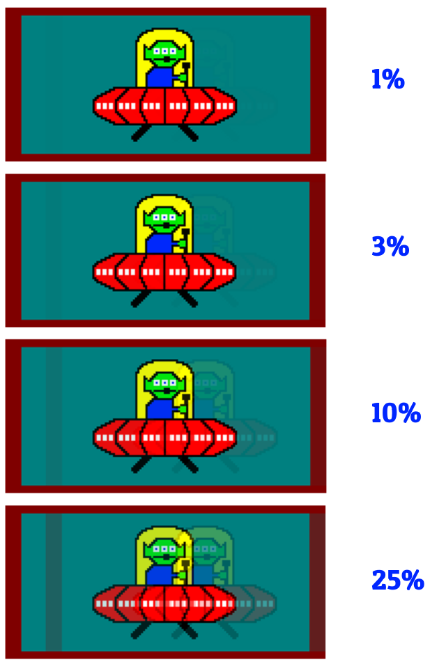
Fantastic idea and we've tried to work on these but these are extremely hard to do at a high quality;
Yes, this is what some manufacturers have worked on -- This is already being done in the industry. However, there are sometimes more drawbacks than benefits. It's softer but the quality of blur reduction is much worse because of multiple law-of-physics problems that is super expensive to solve.
In fact, Blur Busters was originally at the domain name
www.scanningbacklight.com before it renamed to
www.blurbusters.com due to my old Arduino scanning backlight experiments the
idea that John Carmack blessed, that convinced me to start Blur Busters. Do a Whois, I own scanningbacklight.com since 2012 -- the very idea you describe.

I've written about this in year 2013-2014:
Electronics Hacking: Creating a Strobe Backlight
Later on, this work helped a lot of manufacturers decide to add a strobe backlight, and I have helped a few manufacturers, and there's an open source 4-segment scanning edgelight in the Zisworks 4K 120Hz diplay that can do 540p 480Hz. (
http://www.blurbusters.com/480hz)
For a good scanning backlight, the problem making it work well is eliminating internal backlight light leakage from the ON segments to the OFF segments. It's VERY hard to do that -- you need to scrap the entire assembly behind an LCD and create excellent light optics that focusses the backlight only to the right segments. If there's even just a 5% light leakage to the opposite end of the screen, you have a 5% strobe crosstalk elsewhere on the screen.

To build a VERY good scanning backlight, you want to make sure your GtG is quite practically complete in all areas that will receive between 3-10%+ light leakage. So you have to initiate GtG far ahead of the scanning light line.
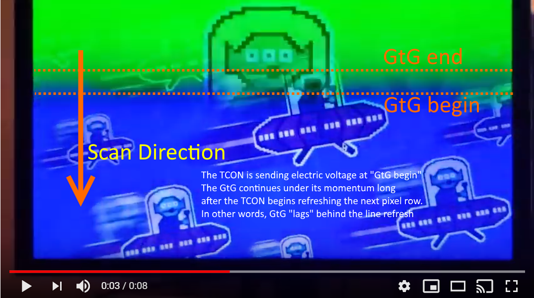
On steady state light, the LCD GtG creates a scrolling fadezone as seen in
high speed videos.
 Light Leakage Problem In Scanning Backlights
Now adding a scanning backlight to this, you need to illuminate a row of LCDs far away from the GtG fadezone (but as close as possible, to minimize latency). More light scatter problems, the more distance between GtG zone and scan-flash zone you need (and thus more lag relative to a CRT). Too much light scatter, and no area of the panel is free of the flash and you've got unsolvable strobe crosstalk.
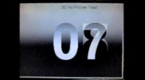
For years, LCDs could not cram GtG into VBI, and you got 3 refresh cycles ghosting into each other:

(This screen is showing 06, 07 and 08 simultaneously from
http://www.testufo.com/flicker test).
This panel is impossible to strobe (or scan-backlight) without strobe crosstalk. It was not until most of GtG pixel transitions became a tiny fraction of a refresh cycle, before strobing finally became practical.
Now, I'm obviously interested in restarting the scanning backlight experiments thanks to newer 240Hz 1ms IPS panels which are astounding quality. Best strobed quality I have ever seen in an LCD, bar none.
_____
Open invitation to hobbyists to restart scanning backlight experiments
If they are paired up with a really good voltage-boosted RGB scanning backlight, that would be sweet -- the problem is the time & expense assembling excellent optics from scratch (e.g. a full array of parabolic lens, or LEDs that have those built-in into them, combined with other optics that focuses them only on areas of interest, while NOT looking beady.

Currently, it has been easier to get CRT clarity with a full-flash strobe backlight, because of the light leakage problem of scanning backlights. The best strobe backlights outperform the majority of scanning backlights. In the past, you have to spend a huge amount of money (turning a monitor from $500 to a $5000 monitor) to pull off a good scanning backlight. But there are now some clever solutions to make a scanning backlight much cheaper.
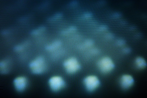
Focussing the LEDs forward means you get beads. But trying to diffuse the beady-look means you will leak light all over the panel (including the far reaches), creating annoying strobe crosstalk (faint ghost images).
Fantastic ideas and talk though and I'd like to hear solutions of ideas of how to solve the law-of-physics problem of cheaply de-beading a FALD without light leakage to far reaches of the LCD panel. (This is why good FALD HDTVs are so fracking expensive) I've come up with
some inventions in display testing so that is more the Blur Busters sauce nowadays, but our legacy is indeed practical strobe backlights that has revolutionized LCD motion blur reduction nowadays.
Digital De-Beading / De-Halo Algorithms
One possible is a GPU shader that does digital de-beading of backlights. Some TV manufacturers now do this to have more focussed FALD with less halo problem. The halo problem is exactly the same problem as strobe crosstalk during scanning backlights! Light leakage. Now, if you display gray in one part of the backlight, and you predict light leakage, you can display a darker gray or even black on the LCD, and then the pixel will be the correct brightness. Now you have less leakage issue. But it's even worse for scanning backlights because you don't have LCD black helping keep things dark. Another "OFF" part of the screen that needs to stay OFF (due to need to keep GtG transitions in dark) may have LCD panel white or bright colors in an OFF part of the backlight, and that amplifies light leakage visibility compared to haloing. So light leakage is much more critical for scanning backlights than for local dimming.
Doing de-beading digitally (if you have 10-bit or 12-bit color depth) solves the problem. I think this can now be done cheaply with a GPU shader, and solve a major scanning backlight expense problem without adding light scatter. The problem is creating the de-beading mask (alpha), but this could be done by an ultrasensitive photodiode and illuminating 1 pixel at a time, and running an overnight recorder. Cheap Arduino stuff that can be done DIY. And can be done realtime to Windows/games with less than a 5% performance penalty on most GPUs nowadays (albiet not slower GPUs or laptop GPUs).
Don't Forget Importance of Overdrive for Strobing / Scanning Backlights
Also, another thing is we need better overdrive for strobe or scanning backlights. We need GtG to be as close to 100% clean as possible (no overshoot or undershoot). Overdrive lookup tables are superior to Overdrive Gain formulas when done with either strobe backlights or scanning backlights. You want the LCD pixel color at the exact correct color the moment of the flash at the specific area of the screen. Some strobe backlights use a Y-axis variable overdrive strength, to accomodate the time-differential between scanout-in-dark versus global all-at-once flash, and that helps a lot. This can be done by simply incrementing overdrive gain (e.g. Strength 50 through Strength 80 on a Overdrive Gain 0...128 scale) from top to bottom in a linear fashion. This obviously, needs to be calibrated with a test pattern such as
http://www.testufo.com/crosstalk .... But this reduces strobe crosstalk even further, up to the limit of law-of-physics. There are issues near fullblacks and fullwhites (fully saturated colors) since you need overshoot room below black and above white, for accurate overdrive at the extreme edges of the color gamut. That's very hard, so some vendors reduce contrast ratio sligthly (reduce digital gamut to only 90-95% original) to improve GtG accuracy at the moment of strobe flash -- that's why LightBoost had degraded colors. But with even faster LCDs (sub-1ms LCDs) this becomes less and less necessary to reduce gamut to improve strobe. Anyway, this is less than 10% of my "Blur Busters Einstein Brain", but it underscores how complicated high quality strobing or scanning-backlight can be.
Overdrive can be simultaneously combined with de-beading / de-haloing algorithms
A more advanced implementation would combine into a hybrid overdrive that is light-leakage aware. You just want the correct number of photons emitting for a specific pixel, and so accomodating all the complex factors (light leakage, GtG inertia, time differential between GtG-start and strobe-flash, etc) to try to get as close as possible to the correct number of photons emitted per pixel. It's getting easier and easier, but the algorithms can be horrendously complex. This separate the $500 displays from $5000 displays. The best LCD HDTVs has had some really advanced Ph.D math formulas in their FPGAs / ASICs / GPUs. But we can get 90% as good with just pure hobbyist math that is understandable by a high school graduate.
----
(This talk is why I love running Blur Busters. This used to be a hobby, even as it turned into a business for me --
Blur Busters Services).
P.S. Great animated artwork! Whose animations were these? I would love help from whomever did those animations, to create some "related" animations in the future. Did you create those animated GIFs yourself? Are they of a real experiment or a photoshop? I could use such skillz to create educational animations that raise the state-of-art of the industry. There's other explanation animations I need to explain strobe crosstalk behaviours and the importance of millisecond and sub-millisecond GtG for cheap-to-engineer high-quality strobe backlights. That's why I'm so enthusaic about 240Hz 1ms IPS as excellent candidate to get closer to CRT quality (for strobe or scanning backlights)....


