Just created diagrams.
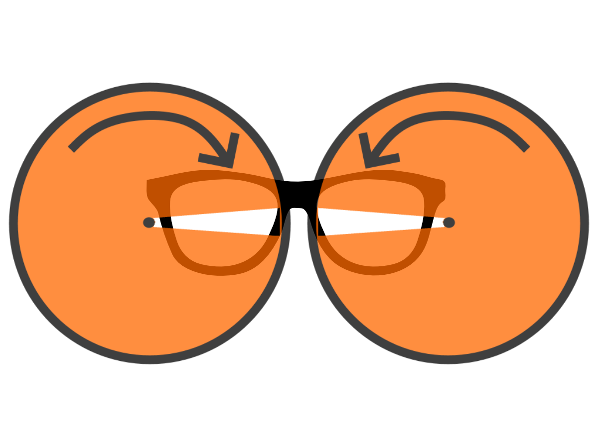
Option 1: Two Shutters
Pros:
1. Similar behavior for both eyes
2. Vibrations cancel each other out with fast contra-rotating motors (3600 RPM at 60Hz unless you use multiple slits per wheel, see below!)
Cons:
1. Requires two synchronous motors (or one center motor with gears to the two side wheels)
2. Movement of head will produce mis-sync artifacts.
__________________________________________________________
Option 2: One Shutters
Pros:
1. Simpler to build.
Cons:
1. Offset weight
2. Offset vibrations may make for uncomfortable viewing.
3. Movement of head will produce mis-sync artifacts.

__________________________________________________________
Option 3: Table Edge Mounted Shutter (RECOMMENDED)
Pros:
1. Easiest to build, fewer components, can use a vise to hold apparatus
2. Vibrations won't interfere with your head
3. Position can easily be calibrated (movement of monitor + shutter to ideal positions), removing the human-head-position uncertainity
4. Compatible with projectors too (putting it in front of projector lens, then everybody can view the same low persistence on the screen)
5. Easier to calibrate head-to-wheel distance simply by moving head closer/further away from wheel.
6. More comfortable
Cons:
1. Not wearable
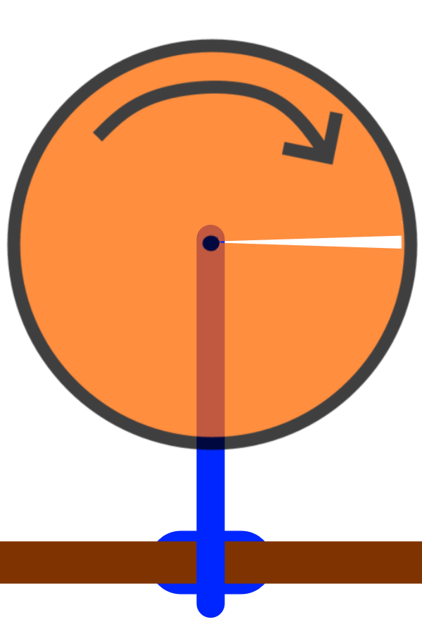 This is the RECOMMENDED technique for mechanical strobing of a display
I super-strongly recommend option 3 as a starter build -- more than 10x easier to succeed. Plus more flexible/modifiable for different displays & even use for projectors too!
- Make sure you design your wheel big enough to accomodate both eyes.
- A 12-inch-wide wheel should suffice.
- BONUS TIP: You can add multiple slits to the wheel (2 slits) and simply spin the wheel at half speed, if you're concerned about off-center-gravity vibrations. So one slit at the left/right edge of the circular rolling shutter.
__________________________________________________________
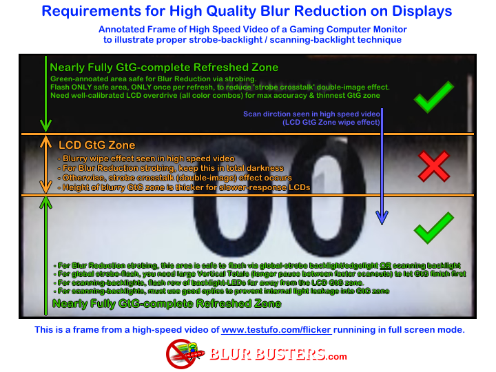
Warning: This Does Not Solve All Problems
Instead of 1 slit you will need multiple slits so that you can slow-scan downwards at a velocity similar to the refresh scanout. You'll probably want maybe 3 or 4 or 6 narrow slits per wheel (applies to any of the 3 options above) so you can view through the slit closer, you will need to experiment with slit position so that your rolling-shutter velocity roughly matches the top-to-bottom scan velocity, and you'll probably need separate wheels for different Hz for this very reason.
Alternatively, you could work from the reverse direction (choose a horizontal-scanrate-multisync panel and then optimize scanout velocity (of a multisync panel) with Large Vertical Totals to speed up / slow down the scanout of a panel to match an unmodifiable strobe wheel).
Rolling shutters is what many old 35mm movie projectors do to hide the blur of the filmreel moving from one frame to the next.
(
Google Images Search). You're simply commandeering this technique to hide the GtG fadezone while lowering the persistence of a sequential-scanout sample-and-hold display.
When using this method to do low-persistence of an LCD or OLED, you will need a much narrower slit than what film projectors use. Slit width as percentage of the distance to next slit, will be your persistence percentage. As a boilerplate recommendation, I recommend 10% persistence, so your wheel's rotational surface area will be 10% slit by surface area. Due to the way human vision cones out, it may a 10% slit may actually end up closer to 20%-30% persistence.
If you cut all the way to pretty close to center, make sure to cut slits out in pie-style, not straight slits, because outer parts will scan faster than the inner part. Now, if you need extra structural, don't cut slit all the way to center but closer to a Phenakistoscope wheel (but with longer slits).
Also, when viewing through the slit, view the slit from a few inches away, rather than extremely close to the slit. You'll have lots of fun testing head-to-wheel distance.
Optimization: Use Multiple Slits Per Wheel
You want one slit scrolling past per refresh cycle, which means a 1-slit wheel needs to spin 3600 RPM for 60Hz displys, or 7200 RPM for 120 Hz displays. So you'd need a very strong wheel, and it might get dangerous.
The fewer slits you have (or just 1 slit), you will need to spin the wheel slower.
For a 60Hz display:
- A 1-slit wheel spins 60 cycles per second (3600 RPM)
- A 2-slit wheel spins 30 cycles per second (1800 RPM)
- A 3-slit wheel spins 20 cycles per second (1200 RPM)
- A 4-slit wheel spins 15 cycles per second (900 RPM)
- A 10-slit wheel spins 6 cycles per second (360 RPM)
The more slits, the easier it will be because of:
- Slower motor spin speed
- Easier to get the picture brighter with less crosstalk and fewer artifacts
- More of the screen will be hidden more reliably with close human-head-to-wheel viewing distance, because of narrower slits.
- A smaller wheel is possible with more slits because you're more easily able to put your head closer to the spinning wheel.
- Viewing the slit too closely will cause you to view too much of the screen surface. And you're forced to use a bigger wheel when you're using a more distant viewing distance.
TIP: Optimize To Slow Wheel Speed So You Can Use Simple CARDBOARD
If you use enough slits, you can spin slow enough to just use simple cardboard or construction paper for strobe wheel!
(Just like a DIY Phenakistoscope / Zoetrope / Etc project.)
Cardboard shutter wheels are common in other non-display projects, as they are based on the 19th century invention of moving pictures. You're just commandeering this technique for mechanical strobing of an LCD display. Thinner slits were well known to darken picture but make motion clearer (less motion blur) -- slit size optimization is an art of the 19th century which you will still need to do in the 21st century for mechanical strobe for display motion blur reduction.
Except with a strobe wheel:
- You use the same cardboard wheel but with NO PICTURES
- Instead, you view a display through the cardboard wheel.
- If you are starting out can begin with small slits only suitable for one eye (for simpicity) before going to larger wheels or double wheels (for both eyes).
- The great thing about cardboard is you can keep trying and trying with different slit sizes and wheel sizes.
Optionally, if you have difficulty visualizing how to fix problems, then if you want to speed up debugging, I highly recommend a 960fps high speed camera. I don't need it because I am good at visualizing displays (my head can emulate display algorithms -- that's how I invented some TestUFO patterns) but not everyone can do this.
- Almost any Samsung Galaxy S9, S10, S20 can act as your 1000fps high speed camera.
- A cheap Sony Experia XZ2 Premium from eBay for about $200 if you just want a cheap 1000fps HD camera for DIY display engineering.
- You can use this on the display (to ascertain its scanout behavior)
- You can use this with the spinning wheel (to double check spinning velocity and sync with display).
Bottom line for easier flexible debugging:
- Table mount method
- Larger-than-necessary 18+ inch wheel (much more flexible)
- Many more slits (that only begins about ~3 inches outwards from the wheel center, to keep wheel center strong), perhaps 10 or 20 slits so your spinning speed is within range of cheap motors.
- With a slow enough spin speed, you can just use cardboard or construction paper & an exacto knife!
So you can build many different wheels with different slit sizes and different number of slits.
Recommended Easy Journey
1. Table edge mount with a vise or
modified VESA mount pole.
2. At least 10 slits, to keep spin speed slow and allow use of cheap cardboard
3. Experiment with a few wheels with cheap cardboard + scissors/Exacto knife, so you can repeatedly experiment with different wheels.
4. Begin with direct motor power (analog potentiometer for motor speed control) and calibrate the spin speed manually.
5. Only after then, start adding an Arduino to control motor speed (may need to swap motors to one you can control exact speed of)