
I write CRT shaders and own a relatively high end LCD (Eve Spectrum) and a couple of Sony PVM CRTs. I have a question about trying to preserve the black pixels in between the scanlines and phosphor mask when scrolling in a vertical direction (against the scanlines).
Both my CRTs and LCD lose the visibility of them as a game scrolls (Legend of Zelda SNES) I think due to the persistence of vision optical illusion. However my LCD seems to lose them more and I'm trying to see if there is anything I can do to bring them back i.e break the optical illusion.
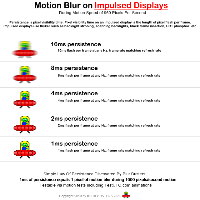
It seems I want the opposite of what the Blur Busters high frequency persistence of vision tests are doing i.e I want the black bars to be visible not get blurred over. This seems to be a different problem to what is normally discussed on blur busters with the space ship moving across the screen. Instead I want the black pixels which are in fixed positions (don't move) to be visible.
Maybe the problem is purely fixed by simulating a scanning electron beam? Has anybody experimented with simulating multiple electron beams? As in one per power of 2 pixels or something at high refresh rates?
Persistence of Vision CRT's & LCD's

Re: Persistence of Vision CRT's & LCD's
Not sure if this is something that can even be done. A CRT shadow mask can make it less obvious, at least to me, because it makes the image grainier so the disappearance of the blank scanlines becomes less jarring.MajorPainTheCactus wrote: ↑20 Feb 2022, 18:20Both my CRTs and LCD lose the visibility of them as a game scrolls (Legend of Zelda SNES) I think due to the persistence of vision optical illusion. However my LCD seems to lose them more and I'm trying to see if there is anything I can do to bring them back i.e break the optical illusion.
For example with this:
- without_mask.png (21.2 KiB) Viewed 3757 times
But with this (a shadow mask from Lottes):
- with_mask.png (36.74 KiB) Viewed 3757 times
Again, the blank scanlines still disappear to the human eye when scrolling vertically. It's just that the shadow mask is still visible and thus the missing blank scanlines seem less noticeable, at least to me.
Steam • GitHub • Stack Overflow
The views and opinions expressed in my posts are my own and do not necessarily reflect the official policy or position of Blur Busters.
The views and opinions expressed in my posts are my own and do not necessarily reflect the official policy or position of Blur Busters.
-
Chief Blur Buster

- Site Admin
- Posts: 11653
- Joined: 05 Dec 2013, 15:44
- Location: Toronto / Hamilton, Ontario, Canada
- Contact:
Re: Persistence of Vision CRT's & LCD's
Remember that on ALL sample and hold displays, the finiteness of the refresh rate is an unavoidable laws of physics constant. There's no way to fix this without adding black periods between refresh cycles in a sub-refresh manner (control of pixels in finer granularity than 1/60sec).MajorPainTheCactus wrote: ↑20 Feb 2022, 18:20I write CRT shaders and own a relatively high end LCD (Eve Spectrum) and a couple of Sony PVM CRTs. I have a question about trying to preserve the black pixels in between the scanlines and phosphor mask when scrolling in a vertical direction (against the scanlines).
Both my CRTs and LCD lose the visibility of them as a game scrolls (Legend of Zelda SNES) I think due to the persistence of vision optical illusion. However my LCD seems to lose them more and I'm trying to see if there is anything I can do to bring them back i.e break the optical illusion.
It seems I want the opposite of what the Blur Busters high frequency persistence of vision tests are doing i.e I want the black bars to be visible not get blurred over. This seems to be a different problem to what is normally discussed on blur busters with the space ship moving across the screen. Instead I want the black pixels which are in fixed positions (don't move) to be visible.
Maybe the problem is purely fixed by simulating a scanning electron beam? Has anybody experimented with simulating multiple electron beams? As in one per power of 2 pixels or something at high refresh rates?
Ideally you need to simulate a 60Hz refresh cycle with over a dozen refresh cycles to make it look true-CRT-accurate, so you may want to resort to hardware-based means instead (aka backlight flashing instead) as backlight flashing is your easiest band-aid for the effect that you describe.
Why don't you enable Eve Spectrum strobing? That would fix your problem. That would solve your problem with www.blurbusters.com/strobe-utility-eve as I have already programmed a Strobe Utility for Eve monitors. You can use QFT + 60Hz single strobe to massively reduce strobe crosstalk by refreshing 60Hz refresh cycles in 1/144sec (hiding LCD GtG in VBI), reducing the double-image effect. Then you re-tune with Strobe Utility. It looks MUCH better than default 60Hz, once you re-strobe-tune a QFT mode. Refresh rate headroom is good for improving strobe quality.
Right now I think in two spheres:
Spatial CRT simulation -- like MAME HLSL existing
Temporal CRT simulation -- like my Retroarch BFIv3 suggestion
One can be done, or both can be done concurrently (The Holy Grail).
About software based means, aka RetroArch BFIv3 idea, you will need direct hardware access to multiple refresh cycles per emulator Hz, no way around it, laws of physics of what you need done dictate fine-granularity subrefresh control of pixels (whether by frames or by backlight). All sample and hold displays behave differently (whether Persistence or vice-versa) for stationary eyes and moving eyes. To get around this requires subrefresh control of pixels, to make graphics as sharp moving and stationary. Minimum requirement 4 refresh cycles (aka 240Hz) for basic CRT rolling scan that looks semi-fake, recommended requirement 16 refresh cycles (aka 960Hz) for really accurate looking CRT rolling scan. You can get by with 360Hz (6 refresh cycles per 60Hz).
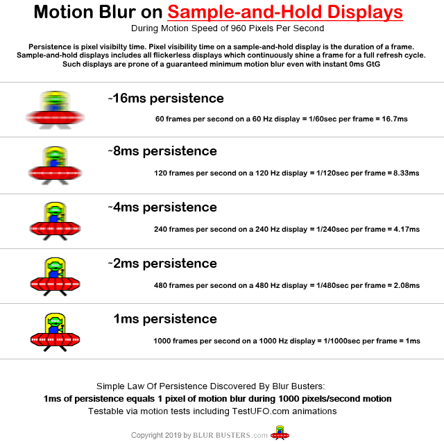
Blur Busters Law dictates that 1ms of pixel visibility time translates to 1 pixel of motion blur per 1000 pixels/sec. The only way to shorten pixel visibility time is:
Strobing: Eye-tracking-based motion blur can be never less than flash length (pixel visibility time). Whether it's software-based strobing (BFI is limited to refresh cycle granularity), or hardware based strobing (backlight can be precisely controlled)
Sample-and-hold: Eye-tracking-based motion blur can never be less than refresh cycle time (pixel visibility time). But you need unique frames for this, so you have to go above 60fps to reduce motion blur.
You can read the Blur Busters research at blurbusters.com/area51 or surgically read articles such as GtG versus MPRT to understand this better.
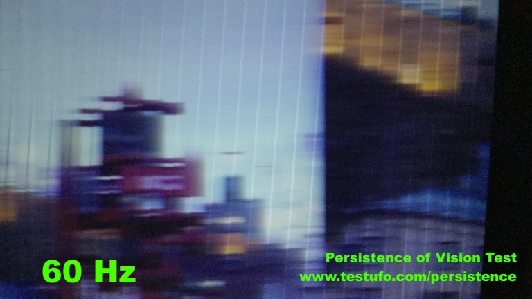
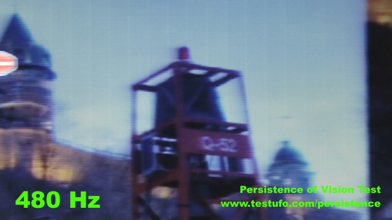
Stationary pixels will always be perpetually blurred. That's why www.testufo.com/persistence horizontal resolution stays constant no matter how dense you make the vertical lines -- and the horizontal resolution doubles whenever you double Hz, and that test was designed for 480 Hz displays (480 Hz article):
OPTION 1 --
Easiest is to just enable strobing on Eve, and OPTIMIZE the strobing (create a custom resolution to milk the refresh rate headroom into QFT headroom to cram more LCD GtG into VBI hidden by human eyes -- a 60Hz mode with the 144Hz scanrate and a VBI bigger than the visible image). This is because you're forced to work within the confines of the limitations of current display Hz, you will necessarily have to enable strobing.
OPTION 2 --
Get ready for the future of ever-increasing Hz to emulate CRTs more accurately using more refresh cycles per CRT Hz. However, since you are a shader programmer, would you program a electron beam emulator if somebody pitched you a 360Hz+ monitor? I would love to see multiple open source implementation (including GPL and Apache/MIT versions) of electron beam simulators for multiple projects, emulators and non-emulators. That said, you'll also want to study up on Area 51 to understand Hz/BFI science better to the "Blur Busters Law" simplicity...*
*Remember to process the spatial CRT emulation and temporal CRT emulation separately. They don't need to be dependent on each other (unless you need subrefresh beam racing, e.g. drawing emu raster slightly ahead of real raster, using the VSYNC OFF frameslice beam racing pioneered by my Tearline Jedi and now utilized by some emulators).
Long term I want emulators to migrate to an optional ability to output one pixel row at a time (or a series -- a frameslice), so downstream displayer modules can optionally choose to beamrace it (e.g. display emulator images in FPGA-league sub-refresh latencies).
Head of Blur Busters - BlurBusters.com | TestUFO.com | Follow @BlurBusters on Twitter

Forum Rules wrote: 1. Rule #1: Be Nice. This is published forum rule #1. Even To Newbies & People You Disagree With!
2. Please report rule violations If you see a post that violates forum rules, then report the post.
3. ALWAYS respect indie testers here. See how indies are bootstrapping Blur Busters research!
-
MajorPainTheCactus
- Posts: 6
- Joined: 20 Feb 2022, 18:06
Re: Persistence of Vision CRT's & LCD's
Yes so Ive already added my own shadow mask:
https://forums.libretro.com/t/sony-pvm- ... ader/36109
But I'm not sure this is really what I'm after.
There is definitely a clarity to the black lines on a CRT that I don't see on a sample and hold display. What is it that is causing this? As I say this seems to be the opposite effect of increasing refresh rate I.e improving the clarity of the scanlines themselves - at the expense of the black between them. I'm assuming its purely to do with the beam scanning?
I'm assuming you can get a similar effect by having many virtual beams scanning different lines? I'm guessing back light strobing would help but it doesn't seem to. Maybe I need an OLED backlight strobe?
- Screenshot_20220217-222425.jpg (2.53 MiB) Viewed 3713 times
But I'm not sure this is really what I'm after.
There is definitely a clarity to the black lines on a CRT that I don't see on a sample and hold display. What is it that is causing this? As I say this seems to be the opposite effect of increasing refresh rate I.e improving the clarity of the scanlines themselves - at the expense of the black between them. I'm assuming its purely to do with the beam scanning?
I'm assuming you can get a similar effect by having many virtual beams scanning different lines? I'm guessing back light strobing would help but it doesn't seem to. Maybe I need an OLED backlight strobe?
-
Chief Blur Buster
- Site Admin
- Posts: 11653
- Joined: 05 Dec 2013, 15:44
- Location: Toronto / Hamilton, Ontario, Canada
- Contact:
Re: Persistence of Vision CRT's & LCD's
Your new post is very confusing. Without a pursuit-camera video of the effect you're describing.MajorPainTheCactus wrote: ↑21 Feb 2022, 16:12There is definitely a clarity to the black lines on a CRT that I don't see on a sample and hold display. What is it that is causing this? As I say this seems to be the opposite effect of increasing refresh rate I.e improving the clarity of the scanlines themselves - at the expense of the black between them. I'm assuming its purely to do with the beam scanning?
I'm assuming you can get a similar effect by having many virtual beams scanning different lines? I'm guessing back light strobing would help but it doesn't seem to. Maybe I need an OLED backlight strobe?
The answer may be yes or no depending on what you're trying to explain -- now that I'm not sure what you're trying to explain.
A video is worth a thousand words. Can you use a smartphone handwave pursuit camera to describe what your eyetracking is doing, on CRT versus LCD?
In a shotgun fashion (because I am not sure which of the multiple possibilities you are describing), I will try to describe multiple spatial and temporal effects that is at play:
As you already learned, displays behave differently for stationary eyes versus moving eyes. To help further, I need more description of the important scientific input variables (eye motion, display motion) necessary for me to accurately answer you, so I have one important question:
QUESTION
There are four situations where displays look different:
1. Stationary eyes, stationary image
2. Stationary eyes, moving image
3. Moving image, stationary eyes
4. Moving image, moving eyes
Which of the four situations apply to your blurring problem?
Can you please describe when your problem occurs? Only (4) or (2)+(4), or (2)+(3)+(4)?
This will instantly activate my Einstein Brain and give you an accurate explanation.
Long term, the only fix-all is accurate CRT beam emulation to fix (1)+(2)+(3)+(4) simultaneously, while having the necessary nits (CRT beams can exceed 10,000 nits) and the ability to simulate phosphor fade in a subrefresh manner. Full software control of subrefresh behaviour will require ultrahigh refresh rates.
But one of the four items above may be fixable on your Eve monitor, DEPENDING on how to answer the above important question. Is your problem (1) and/or (2) and/or (3) and/or (4)? There can be multiple things occuring simultaneously.
Item 1: Stationary eyes, stationary image
This is a 100% spatial problem and has nothing to do with sample and hold. There's no temporal behaviour (time-based behavior) when we're dealing with static eyes and static images. And thus sample-and-hold (a temporal technology) is completely non-applicable here. So I will describe another cause (to interrupt a wild goose chase to a red herring).
Problems with black gaps between scanlines, relating to this item has nothing to do with sample and hold
Now if you subsequently say the problem is (1) stationary eyes, stationary images, then it has NOTHING to do with sample-and-hold, because:
(A) CRT electron beam is over 10,000 nits for a brief instant (that's why it overexposes high speed video frames).
Emulation of CRT will fail to do this, until you have access to a 10,000+ nit digital display
(B) CRT phosphor dots are sometimes over 1000 nits each average, to compensate for the black gaps between scan lines. A lot of the surface of a tube is completely black, so to get 200 nits with only 25% phosphor coverage, requires 800-nit phosphor dots.
Emulation of CRT will fail to do this, until you have access to a high-nit display, especially one that can do good blacks
(C) The resolution of 4K displays is not always even enough to accurately simulate phosphor dots, unless you're simulating a very low resolution CRT.
One workaround for this is to intentionally configure your shader to blur the phosphor dots so they fill more of the black space around them. The blurring makes the image brighter (to compensate for LCD's inability to reach 10,000 nits), but the blurring action can make the gaps between phosphor dots smaller.
For item (1), this science has NOTHING to do with sample and hold.
Sample and hold comes into play only for items (2),(3),(4).
The lack of nits for each pixel (between black gaps) is why CRT filters look very dull on most LCDs -- the individual LCD pixels are not made as bright as their original CRT counterparts to compensate for the black gaps. Also, contrast ratio of LCDs is lower (1000:1) so this adds further to the washed-out-colors-look of may CRT filters.
So it's a shader fine-tuning compromise, e.g. color saturation adjustment, pixel erode/blurring algorithms (reduce black gaps in order to make phosphor dots bigger to keep up colorfulness/brightness). But too much blurring and you're overlapping the primary colors -- and then color saturation drops like a rock with CRT filters in order to increase brightness (because you can't do 10,000 nit pixels yet on desktop displays). This is simply caused by other problems than sample-and-hold, so "sample-and-hold" would be a mis-blame if your main issue is #1. It's a 100% spatial problem, not a temporal problem (not sample and hold).
Item 2: Stationary eyes, moving image
In this situation, motion blur doesn't apply here. You do get stroboscopic effects, aka The Stroboscopic Effect of Finite Frame Rates. 60Hz CRTs and 60Hz sample-and-hold has very similar stroboscopic effects for stationary-eye moving-image situations. Also neither situation generates motion blur. So this item is probably not applicable to your situation.
But it's important to properly understand the science of item #2, at least in an understanding of creating a temporal component of a CRT shader.
Item 3: Moving eyes, stationary image
Persistence always applies here. Stationary pixels are blurred across your moving retinas, in accordance to Blur Busters Law (1ms of sustained pixel visibility time translates to 1 pixel of eye-tracking motion blur per 1000 pixels/sec motion).
This applies to both scaled and unscaled pixels. That's why motion blur scales up proportionally if you add 200% browser zoom to www.testufo.com -- the blur trail pixels size stays relative to the original size of the pixels (scaled). So Blur Busters Law can be kinda applied to the upscaled pixels or upscaled scanlines.
So if you're eyetracking upwards or downwards, the scanlines will vertically blur filling the gaps. Like a vertical version of www.testufo.com/eyetracking -- you could rotate your LCD display 90 degrees or tilt your head 90 degrees. The scanlines gets eyetracking-blurred during vertical eye movements, filling the black gaps and diminishing the CRT-scanline-feel.
Another point of view: Black gaps between scanlines are always stationary, so from the POV of black gaps, it's a "stationary image" embedded between the moving imagery within the visible scanlines.
Item 4: Moving eyes, moving image
Moving images still have static pixels because it's a series of static images to simulate a moving images. Human eyes are analog, but the frames are stepping. Your eye position is in a different position at the end of a refresh cycle (T+1/60) than beginning of refresh cycle (T+0/160). But the static frames of a refresh cycle are static for a full 1/60sec. So you get the equivalent of 1/60sec motion blur.
[url=https://blurbusters.com/wp-content/uplo ... hutter.png]
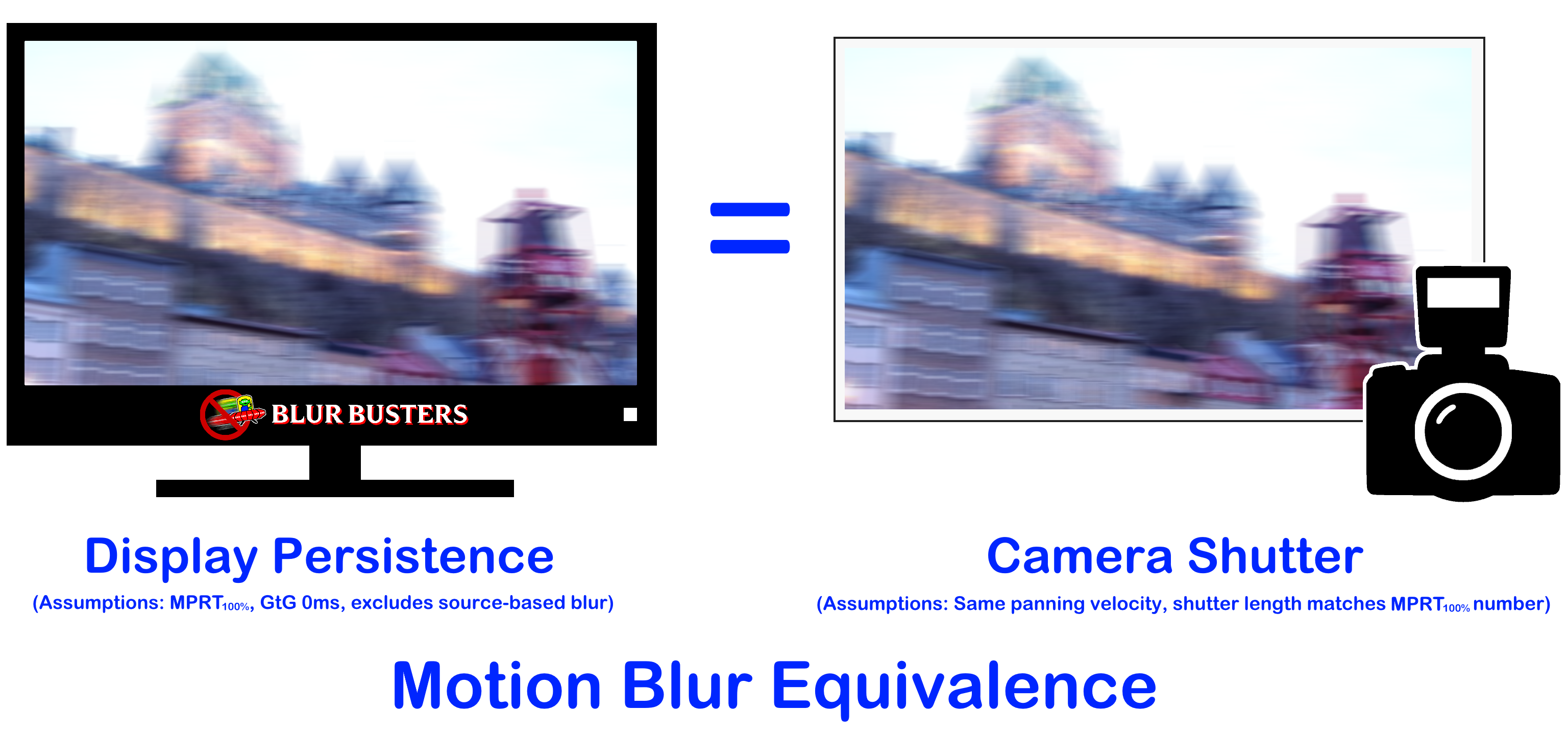
This is why doubling Hz halves browser scrolling motion blur. On a 240Hz display, browser scrolling motion blur is 1/4th of a 60Hz sample and hold, and on a 480Hz display, browser scrolling is 1/8th of a 60Hz sample and hold. It follows Blur Busters Law.
To turn sample and hold into an impulsed display requires software BFI, but software BFI is limited by the refresh cycle granularity. So any subrefresh BFI or rolling scan BFI (like emulating a CRT electron beam), blur reductions is limited by the shortest possible sample and hold refresh cycle you can achieve on your display.
For an Eve Spectrum 4K144, with strobing disabled, you can't get less than 1/144sec motion blur, no matter what kind of CRT simulation algorithm you invent. This will be a laws of physics that affects items (3) and (4) above.
If you can describe if your problem is item (1) and/or (2) and/or (3) and/or (4) -- I can help better explain what your specific limitation is. Also, in my past experience, CRT filters simultaneously have issues with (1) and with (3)+(4) for completely different reasons. (2) is a generally a non-issue in faithfulness of emulation.
Item (1) is spatial only and is caused by lack of single-pixel brightness headroom needed (CRT beams can reach >10,000), while (3)+(4) are temporal and definitely related to the sample-and-hold nature.
Black gaps are a "stationary image" so item (1) and (3) are the most applicable. However, the picture data between the black lines are in motion and will create concurrent arifacts/effects.
The Four Items To Separately Study The Display Science Of
1. Stationary eyes, stationary image
2. Stationary eyes, moving image
3. Moving eyes, stationary image
4. Moving eyes, moving eyes
Some of them require unrelated, independent optimizations.
So you may have more than 1 problem / more than 1 cause.
Only way to bruteforce a fix for all 1+2+3+4 concurrently using only software would be an ultrabright 1000Hz+ display capable of multithousand nits, so you have lots of nit headroom to keep phosphor dots small spatially (improve spatial look) + lots of nit headroom to keep phosphor dots pulsing briefer (improve temporal look). But we don't have 10,000+ nit HDR desktop displays at this time.
So what we're doing today will necessarily be a compromise, depending on your spatial priorities and your temporal priorities.
So I've shotgunned a very broad answer to your question -- did I successfully land on an answer to what you may have been asking?
Head of Blur Busters - BlurBusters.com | TestUFO.com | Follow @BlurBusters on Twitter
Forum Rules wrote: 1. Rule #1: Be Nice. This is published forum rule #1. Even To Newbies & People You Disagree With!
2. Please report rule violations If you see a post that violates forum rules, then report the post.
3. ALWAYS respect indie testers here. See how indies are bootstrapping Blur Busters research!
-
MajorPainTheCactus
- Posts: 6
- Joined: 20 Feb 2022, 18:06
Re: Persistence of Vision CRT's & LCD's
Sadly the backlight strobing doesn't seem to work when HDR is on in Windows (the option is greyed out). HDR is crucial to get the brightness to overcome switching off ~85% of the sub pixels. I do think from reading a lot of what youve been saying backlight strobing is exactly what I want (as it kind of simulates a CRT) but as I say its disabled with HDR.Chief Blur Buster wrote: ↑21 Feb 2022, 16:03Why don't you enable Eve Spectrum strobing? That would fix your problem. That would solve your problem with www.blurbusters.com/strobe-utility-eve as I have already programmed a Strobe Utility for Eve monitors. You can use QFT + 60Hz single strobe to massively reduce strobe crosstalk by refreshing 60Hz refresh cycles in 1/144sec (hiding LCD GtG in VBI), reducing the double-image effect. Then you re-tune with Strobe Utility. It looks MUCH better than default 60Hz, once you re-strobe-tune a QFT mode. Refresh rate headroom is good for improving strobe quality.
Last edited by MajorPainTheCactus on 22 Feb 2022, 17:09, edited 1 time in total.
-
MajorPainTheCactus
- Posts: 6
- Joined: 20 Feb 2022, 18:06
Re: Persistence of Vision CRT's & LCD's
Apologies for my wishy washy explanation - I'm at work at the moment and I need to digest and test what you've said tonight and I'll get back to you.Chief Blur Buster wrote: ↑21 Feb 2022, 16:44Your new post is very confusing. Without a pursuit-camera video of the effect you're describing.
I currently think half my problem is that the Eve Spectrum backlight strobing you implemented is unavalaible when in windows HDR mode which I need enabled.
-
thatoneguy
- Posts: 181
- Joined: 06 Aug 2015, 17:16
Re: Persistence of Vision CRT's & LCD's
OP according to Fudoh from Shmups the Rolling Scan Sony BVM/PVM OLEDs have what you're looking for
https://shmups.system11.org/viewtopic.php?f=6&t=66453
https://shmups.system11.org/viewtopic.p ... 3&start=30
As for why this seems to happen on OLED I have no clue but it might be because OLEDs have very fast pixel response time + the pixel themselves are typical squarewave pixel control like any digitial display as opposed to the analog phosphor fade but that's just speculation on my part.
Also
P.S Scanlines or should I more accurately say "blank lines" shouldn't even be visible on retro games since games like any content were built for low-end consumer TV's of the time. This is why you don't have blank lines on a GBA or on a NIntendo DS/3DS(all of which have low res screens). This is why Street Fighter 2 or Final Fight cabs used curved bubble screens with a very coarse dot pitch(although later on Capcom would use slightly sharper screens with more visible blank lines in the mid 90s) etc.
But that's just my 0.02$ on the subject.
- Attachments
-
- Capture2.PNG (112.3 KiB) Viewed 3490 times
-
- Capture.PNG (56.12 KiB) Viewed 3492 times
-
MajorPainTheCactus
- Posts: 6
- Joined: 20 Feb 2022, 18:06
Re: Persistence of Vision CRT's & LCD's
Thanks for the links I'll have a read.thatoneguy wrote: ↑22 Feb 2022, 16:02OP according to Fudoh from Shmups the Rolling Scan Sony BVM/PVM OLEDs have what you're looking for
https://shmups.system11.org/viewtopic.php?f=6&t=66453
https://shmups.system11.org/viewtopic.p ... 3&start=30
As for why this seems to happen on OLED I have no clue but it might be because OLEDs have very fast pixel response time + the pixel themselves are typical squarewave pixel control like any digitial display as opposed to the analog phosphor fade but that's just speculation on my part.
Also
P.S Scanlines or should I more accurately say "blank lines" shouldn't even be visible on retro games since games like any content were built for low-end consumer TV's of the time. This is why you don't have blank lines on a GBA or on a NIntendo DS/3DS(all of which have low res screens). This is why Street Fighter 2 or Final Fight cabs used curved bubble screens with a very coarse dot pitch(although later on Capcom would use slightly sharper screens with more visible blank lines in the mid 90s) etc.
But that's just my 0.02$ on the subject.
Regards scanlines (scanlines are the lines of colour not the blank lines in between) GBA etc that you mention are all LCD displays not CRT's. All CRT's have scanlines because of how they work, some CRT's have so wide scanlines that you cant see the blank space/dulling in between them but they will have an electron beam scanning lines across the screen.
The artists for high end game studios at the time would most definitely be using professional grade monitors which all had visible blank lines between the scanlines. You can argue whether their intention was for the art to look right on a PVM or whether it was supposed to be for a low end CRT but my guess it was for the PVM as they could see what they were doing as they were working directly on them usually.
-
thatoneguy
- Posts: 181
- Joined: 06 Aug 2015, 17:16
Re: Persistence of Vision CRT's & LCD's
"Scanline" is mostly a terminology thing.MajorPainTheCactus wrote: ↑22 Feb 2022, 16:39
Thanks for the links I'll have a read.
Regards scanlines (scanlines are the lines of colour not the blank lines in between) GBA etc that you mention are all LCD displays not CRT's. All CRT's have scanlines because of how they work, some CRT's have so wide scanlines that you cant see the blank space/dulling in between them but they will have an electron beam scanning lines across the screen.
The artists for high end game studios at the time would most definitely be using professional grade monitors at the time which all had visible blank lines between the scan lines. You can argue whether their intention was for the art to look right on a PVM or whether it was supposed to be for a low end CRT but my guess it was for the CRT as they could see what they were doing as they were working directly on them usually.
It doesn't matter what the technology is. I mentioned GBA/DS/3DS because low res games look correct in them without any blank lines.
The artists had high end sharp monitors for editing and they always had another consumer TV behind it to demo how stuff will look like on a consumer CRT.
They were definitely trying to make stuff as smooth-looking and as little pixelated as possible. They definitely didn't want blank lines(much less thick ones) if they could help it.
Anyways, I have this theory that the TVlines(Horizontal Resolution) of a CRT should match the resolution of the incoming signal(e.g typically a 320x240 window for retro). A coarse dot pitch also helps things too for low res.
To better illustrate what I'm talking about, look at the video below(timestamped) where Final Fight is displayed on a Shadow Mask PC CRT Monitor windowed in 1/3rd of the screen and look at how smooth it looks.
As a bonus here's what FF7 looked like on a typical consumer TV(via composite)

A bit blurry(partly due to composite) but no visible blank lines anywhere.
That said the shader(or CRT?) you posted earlier on this thread looks pretty damn good and the blank lines don't seem as visible in that one.