Slender wrote: ↑09 Mar 2025, 15:33
So disconnecting the PC from grounding does not affect your PC in terms of smoothness/responsiveness etc.?
Exactly. It makes no difference at all. This makes sense, because there are countries in which the national electric code doesn't require grounding and there's certainly players located in these countries, playing games without a problem.
Slender wrote: ↑09 Mar 2025, 15:33
By the way, do you only have a problem with desync when you install a 850w PSU or other problems?
Yes, the desync is by far the most noticeable problem. There's also just terrible hit detection, like shots passing right through people even if they absolutely should hit. I know that this must come from the PSU in my case, because a.) it happens in every game I play, all the time, and b.) it goes away as soon as I switch out the 850W (or a 650W, or a 700W, or a 550W one) out with the 1300W Super Flower unit.
Slender wrote: ↑09 Mar 2025, 15:33
How can I measure voltage with a multimeter while running a full load test on the PC?
That's pretty straightforward. Your motherboard has a 24-pin connector on it. It's the humongous one in the middle and to the right of the board. As your PSU has all black cables, you can't tell which wire is what voltage from just looking at it. You can either know the pinout from doing this countless times, or you can look up pinout diagrams online, one example is this one:
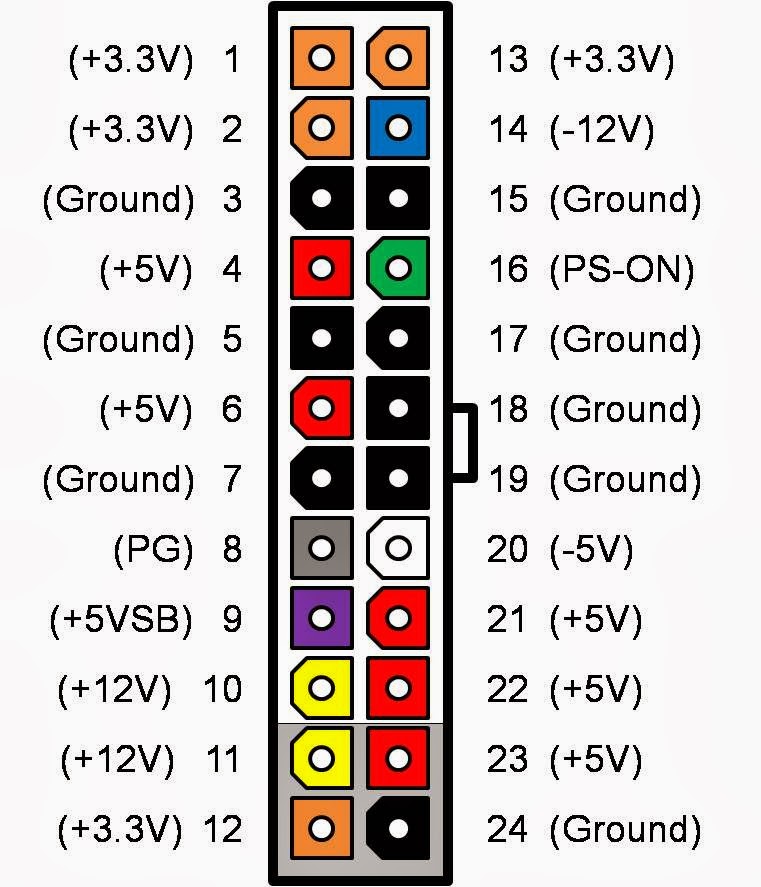 Important:
 The picture shows the 24-pin connector
from "below", as the receptacle on the motherboard would see the connector. When measuring the voltage "top-down", like you're going to do,
flip the image in your head vertically. Otherwise, your measurements won't line up. For example, the two orange +3.3v pins in the top left of the image would sit on the bottom left when looking at your connector from above.
Next, you want to take your multimeter and connect its leads for DC voltage measurements. Then, take the black lead (ground/COM) and probe any ground pin in the 24-pin connector (marked black in the pinout). You can just stick the lead in from the top. Don't force it in too hard, it should read a voltage pretty early and there's no need to force the lead in all the way. Next, find a +12v pin on the 24-pin connector. Stick the lead into that pin, just like you did with the ground lead. Repeat for +5v (red) and +3.3v (orange).
Full computer load can be generated with synthetic tools. One such tool is OCCT, but there are many more.
Put on the load, and only then take your measurements. Measuring the voltages in idle won't reveal problems.
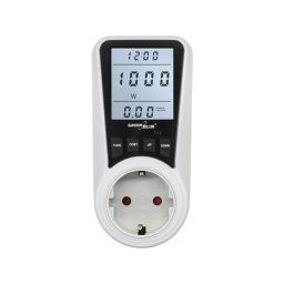
Write down the measurements you've taken with your multimeter. You said that your PC has a power consumption of 500W under full load. Did you estimate this from rough calculations/TDP's, or did you measure this with a power consumption measurement device? Measuring from the wall with a device would be preferred. These power meters usually look like this:
Let's assume 500W is accurate for now. I'm looking at a test report for your PSU right now and it states the following values for 60% load:
Your measurements should line up with this pretty much exactly. If they do, fair enough. Your problem is likely of other origin than PSU/electrical BS. However, if they're different by more than a few millivolts, it might be worth looking into it further. If you want, you can post your measurement results in here.
Slender wrote: ↑09 Mar 2025, 15:33
By the way, setting 240v on my ups solves some problems with 5V and 3.3V
This shouldn't happen. The power supply probably has a large input voltage range, and from looking at the label it supports all input voltages from 100-240v at 50Hz or 60Hz. Changing the input voltage from 230v to 240v should not make a difference at all, especially not for voltage regulation on the minor rails. I would say it's probably coincidence. Germany has a nominal voltage of 230v, however the voltage in my house is more around 240v all the time. There's some times when the voltage drops to about 225v, and it can get as high as 245v. This is normal and to be expected. However, any change in input voltage doesn't change the voltage regulation on any of the rails. And, because of how these PSUs work, this is exactly what should (or rather, shouldn't) happen. What you're seeing is definitely strange, if you can actually correlate input voltage with the voltage regulation on the minor rails. I'd look more into that. Make sure it's not coincidence, though.
Slender wrote: ↑09 Mar 2025, 15:33
now they do not fall below these values.
This implies that they do fall under with your UPS set to 230(?)v (whatever is default for your contry). If so, then there's definitely something wrong with the PSU. It's designed to take a wide range of input voltage and changing from/to 220, 230 or 240v should make zero difference in output regulation. Looking at the test report, the voltages on either rail should never drop below the spec in any loading scenario. Even at 110% load, which would be 935W, the +12v is at +12.088v, the +5v is at +5.045 and the +3.3v is at +3.367v. The load regulation on your PSU is excellent, as good as it gets honestly.
Your next step should definitely be to check your load voltages with a multimeter.