
Apologies -- the excess number of questions has delayed my ability to respond -- workload is high. (Paid time helping manufacturers is priority, forum time is volunteer). If you wish to prioritize which 1 question you want me to answer first, I can answer immediately.
An unspoken gentleman's etiquette for is to throttle to 1 or 2 question per turn -- it's much easier.
DLP BFI for Consoles
-
Chief Blur Buster

- Site Admin
- Posts: 12056
- Joined: 05 Dec 2013, 15:44
- Location: Toronto / Hamilton, Ontario, Canada
- Contact:
Re: DLP BFI for Consoles
Head of Blur Busters - BlurBusters.com | TestUFO.com | Follow @BlurBusters on: BlueSky | Twitter | Facebook

Forum Rules wrote: 1. Rule #1: Be Nice. This is published forum rule #1. Even To Newbies & People You Disagree With!
2. Please report rule violations If you see a post that violates forum rules, then report the post.
3. ALWAYS respect indie testers here. See how indies are bootstrapping Blur Busters research!
-
Chief Blur Buster
- Site Admin
- Posts: 12056
- Joined: 05 Dec 2013, 15:44
- Location: Toronto / Hamilton, Ontario, Canada
- Contact:
Re: DLP BFI for Consoles
There's no difference between DisplayPort and HDMI at the raster VSYNC layer.
All video connections are simply serialization of 2D data into 1D.
VSYNC is unchanged for 100 years!
Every display from 1920s televisions to 2020s HDMI, analog and digital exactly follow this raster sequence:
Please see this thread:
viewtopic.php?f=10&t=9732&p=78261
We've been doing it this way for 100 years on all raster broadcasts (Analog) & raster video cables (DisplayPort, HDMI, VGA, DVI, Component, Composite, RF, Coax, Cable, RG-59, Etc). At the decompressed layer, it's always raster. Left-to-right, top-to-bottom, delivered one pixel row at a time, with exactly the same VSYNC interval in a 1930s TV broadcast and a 2020s HDMI cable.
Winky wink -- bet this answer surprised you -- go back to Blur Busters school before posting the next question, please?
Recommended thread reading before you re-word/re-write your questions:
viewtopic.php?f=10&t=9732
viewtopic.php?f=7&t=8889
viewtopic.php?f=17&t=3234
And buddy, do me one, and save my time by asking the right questions post-research? Love teaching, but make sure you learn pre-requisites before asking these kinds of questions. Thanks!
Head of Blur Busters - BlurBusters.com | TestUFO.com | Follow @BlurBusters on: BlueSky | Twitter | Facebook
Forum Rules wrote: 1. Rule #1: Be Nice. This is published forum rule #1. Even To Newbies & People You Disagree With!
2. Please report rule violations If you see a post that violates forum rules, then report the post.
3. ALWAYS respect indie testers here. See how indies are bootstrapping Blur Busters research!
Re: DLP BFI for Consoles
Thanks Chief, I'll read that later because my knowledge on those things is very low, but to put my central question in layman's, I believe there's no way of an Arduino box extracting sync timings from the HDMI-out of a PS5? Else I'm puzzled over why MitM BFI can't be inserted precisely for the projector to receive.
I'll otherwise get to my reading!
I'll otherwise get to my reading!
Last edited by BFI on 15 Feb 2022, 00:13, edited 1 time in total.
-
Chief Blur Buster
- Site Admin
- Posts: 12056
- Joined: 05 Dec 2013, 15:44
- Location: Toronto / Hamilton, Ontario, Canada
- Contact:
Re: DLP BFI for Consoles
Chief Blur Buster wrote: ↑14 Feb 2022, 01:34Welcome to Blur Busters!smoothnobody wrote: ↑13 Feb 2022, 20:27i just got a QN90A tv + RTX 3080. i've spent the last few days reading about vsync, gsync, adaptive sync, fast sync, VRR. i believe i have a limited understanding, but not quite confident to say i know what i'm talking about. i believe i have been reading outdated information, or just plan wrong information. please correct / educate me.
vsync - limits FPS to refresh rate. adds input lag. if vsync limits FPS to refresh rate, how is this different from manually setting the "max frame rate" to your refresh rate? i tried this, and i got tearing. my understanding must be lacking. i also heard when vsync is on you are actually capping your FPS to half your refresh rate. i turned on vsync, my FPS was not half my refresh rate, so i'm not inclined to believe this, but this has come up enough times that makes me wonder if there is truth to this.
We're the pros in explaining this bleep.
Q: Why do VSYNC OFF and VSYNC ON look different even for framerate=Hz?
Short Answer:
Cables do not transmit all pixels at the same time.
Not all pixels on a screen refresh at the same time.
Pixels are transmitted one at a time.
Pixels are transmitted over the cable like a reading book, left-to-right, top-to-bottom.
Displays are refreshed one pixel row at a time
Displays are refreshed like a reading book, left-to-right, top-to-bottom.
VSYNC OFF means a new frame can interrupt/splice in the middle of the previous frame, rather than between them.
This is what causes tearing.
Long Answer:
Here's a high speed video of a screen refreshing. I'm displaying 60 different pictures a second, one rapidly after the other (via www.testufo.com/scanout). Observe how the screen refreshes top to bottom. It happens so fast, that even at 1080p 60Hz, the next pixel row is often refreshed only 1/67,000th of a second afterwards refreshing the previous pixel row. So you need a very fast 1000fps+ high speed camera to really capture this scanout behavior:
This is also how video cables such as VGA, HDMI and DisplayPort transmits the frames of refresh cycles -- as a serialization of a 2D image over a 1D wire. Like mosaic tiles one tile at a time, or a color-by-numbers fashion coloring one square at a time on graph paper. This is the very old fashioned "raster" scanout, which has been used for 100+ years, ever since the first experimental TVs of the 1920s a century ago -- today even digital displays still refresh in the same "book order" sequence (left to right, top to bottom, transmission of pixels over cable, and refreshing of pixels onto screen.
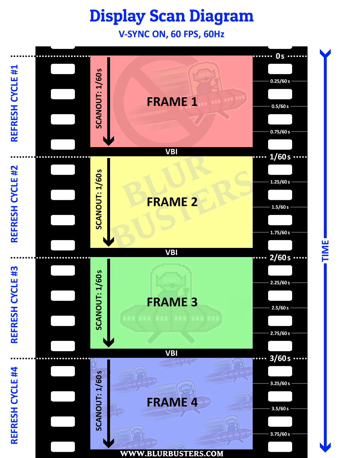
A computer transmits a refresh cycle from computer to monitor one pixel row at a time.
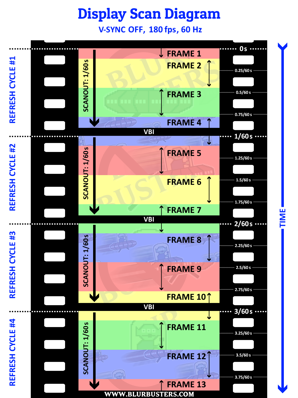
VSYNC OFF -- a new frame can interrupt the current refresh cycle (splice mid-cable-transmission)
VSYNC ON -- a new frame can only splice between refresh cycles (splice in VBI)
Here's diagrams of VSYNC ON and VSYNC OFF.
If you cap framerate=Hz at 60fps, you might be splicing in the middle of the screen at exactly the same location (stationary or jittery tearline), especially with microsecond-accurate frame rate capping.
Now if the frame rate cap is inaccurate and jittery (one frame is 1/59sec and next frame is 1/61sec), the tearline will jump around vertically, depending on inaccuracy of differential of frame rate and Hz, since a tearline will move even if the fps and Hz is 0.001 different.
60Hz is not always exactly 60 -- see www.testufo.com/refreshrate#digits=6 with a microsecond clock to see how inaccurate it can become as an example!
Moreover, VSYNC ON is needed to steer the tearline off the screen into the VBI (the signal spacer between refresh cycles). Other custom tearline steering software like RTSS Scanline Sync or Special-K Latent Sync, can also simulate VSYNC ON via VSYNC OFF, via complex programming -- but explanation is beyond scope of this thread and is explained in other more-advanced threads.
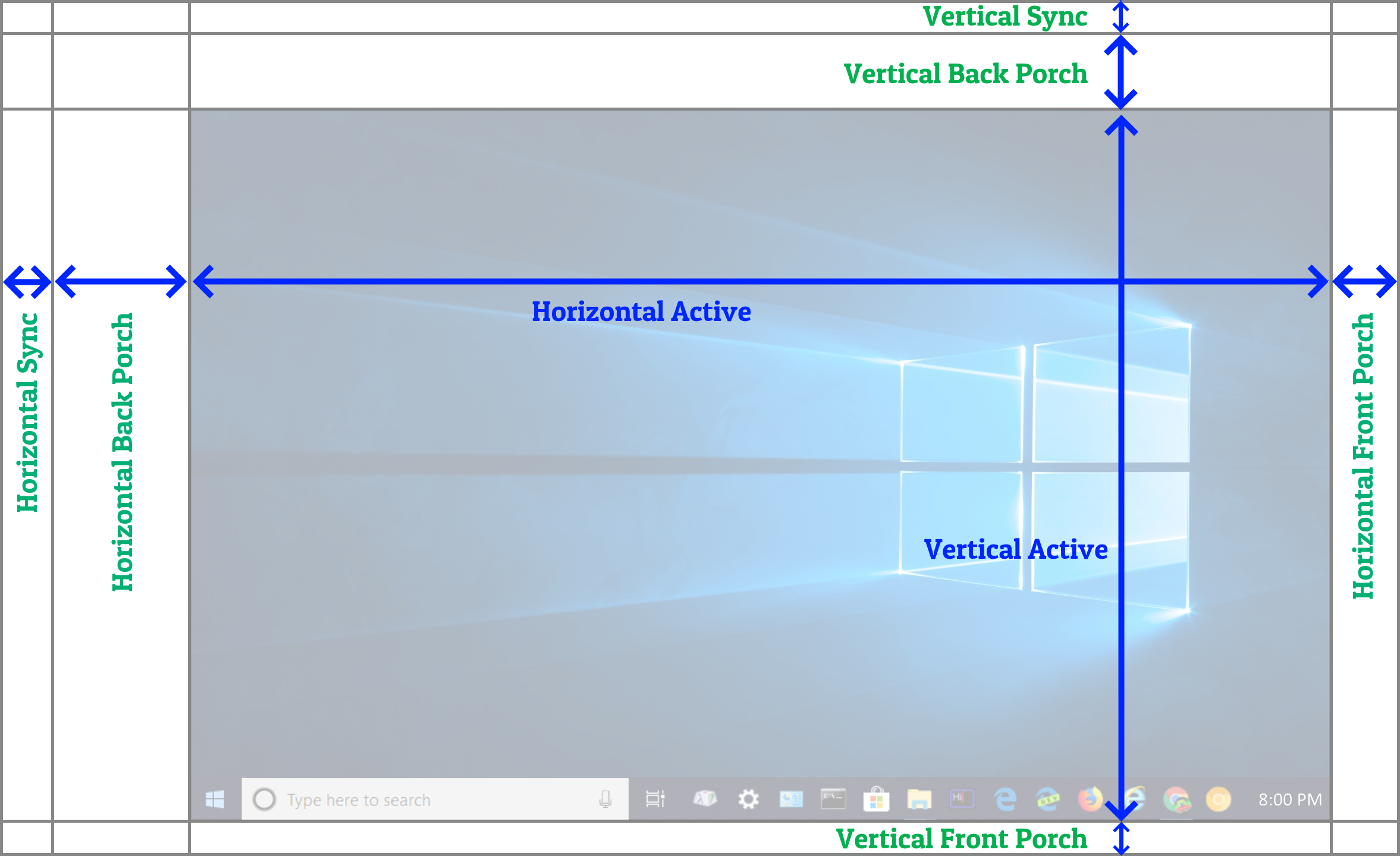
Now, if you ever use a custom resolution utility, you'll observe that there are funky settings such as "Front Porch" or "Back Porch". Porches are simply overscan (hidden pixels beyond edges of screen). This was more common in the analog era, but still is used for digital displays too and digital cables. It's like a larger virtual resolution with the real visible image embedded within. That's how refresh cycles are transmitted over a video cable to help the monitor know how to refresh the image (still a sequential 1D transmission of a 2D image, like a book or a text page -- transmitted left-to-right, top-to-bottom).
Porch is the overscan, and sync intervals are simply signals (a glorified comma separator between pixel rows and between refresh cycles) to tell the display to begin a new pixel row, or a new refresh cycle.
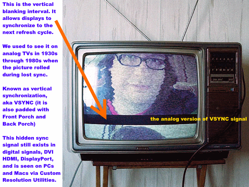
If you are 40+ years old, you probably have spent a lot of time with a CRT tube in the past. Maybe you saw the picture roll (this is called a VHOLD loss, aka loss of "Vertical Hold"), and saw the black bar separating refresh cycles! That's the VBI (VBI = Vertical Blanking Interval = all vertical porches/sync = offscreen stuff separating each refresh cycles).
This is true for both analog and digital signals. For analog, large sync intervals and large overscan was to compensate for the non-square-shaped CRT tube screen as well as the slowness of the electron beam moving to a new pixel row (scanline) or new refresh cycle.
VBI = Vertical Blanking Interval = (Vertical Back Porch + Vertical Sync + Vertical Front Porch)
Head of Blur Busters - BlurBusters.com | TestUFO.com | Follow @BlurBusters on: BlueSky | Twitter | Facebook
Forum Rules wrote: 1. Rule #1: Be Nice. This is published forum rule #1. Even To Newbies & People You Disagree With!
2. Please report rule violations If you see a post that violates forum rules, then report the post.
3. ALWAYS respect indie testers here. See how indies are bootstrapping Blur Busters research!
-
Chief Blur Buster
- Site Admin
- Posts: 12056
- Joined: 05 Dec 2013, 15:44
- Location: Toronto / Hamilton, Ontario, Canada
- Contact:
Re: DLP BFI for Consoles
Wrong. I suspect by "I believe there's no way of an Arduino" you're making incorrect technical assumptions...BFI wrote: ↑15 Feb 2022, 00:12Thanks Chief, I'll read that later because my knowledge on those things is very low, but in layman's, I believe there's no way of an Arduino box extracting sync timings from the HDMI-out of a PS5? Else I'm puzzled over why MitM BFI can't be inserted precisely for the projector to receive.
MitM BFI isn't that hard. It's already being done with Hauppauge TV cards long ago (or any modern video capture cards today), combined with many of the BFI apps already being downloaded, to get blurfree 60fps CRT on 120Hz displays. But it's laggy because TV cards are laggy. Hook your video source (Playstation) to the capture card/dongle, display the live video feed, and run a Windows BFI app on it.
What's hard is programming a lagless-as-possible MitM BFI, because you're forced to buffer the slow-scanout 60Hz input, before beginning the fast-scanout. Waiting for each pixel to arrive one at a time, one pixel after the other in a slow 1/60sec delivery. Modern displays can refresh realtime (draw pixels as they arrive on the cable), but a MitM BFI processor has to buffer-up.
Now, for mechanical strobing, Arduino+LCD can do it more laglessly. You can simply transmit a VSYNC signal over a USB cable (e.g. monitoring via D3DKMTGetScanLine() in a high-priority system tray or windows service thread to get the VSYNC signal from GPU-side -- works on VGA, DVI, DisplayPort, HDMI) to your Arduino, and use a jitter-filter algorithm like the one used for Tearline Jedi or the one used by ad8e (japanese guy with open source project), and successfully get a stable LCD-BFI-quality accurate VSYNC signal even over jittery USB. Since LCD scanout is pretty mechanical-BFI-forgiving, you simply use a strobe phase adjustment (even 1ms jitter error margin will be mostly invisible at 16ms 60Hz, since that's only a 1/16th screen height crosstalk-bar jitter), and eyeball-tune the phase, as a time-offset from the USB-transmitted VSYNC (PC side listens to D3DKMTGetScanLine() API and sends heartbeat over USB to Arduino).
The phase adjustment also fully compensates for unknown absolute display lag too -- you simply eyeball the phase calibration with www.testufo.com/crosstalk -- and call it a day. Don't need to know the cable lag or display lag, just the accurate VSYNC heartbeat and you can monitor it GPU side and transmit the VSYNC heartbeat to the Arduino, not caring a bit fat bleep about what kind of cable it is...
Yes, USB jitter, but it's successfully mathematically filterable to within the error margins needed for functional mechanical LCD BFI. Or you can semi-compensate by microsecond timestamping the VSYNC heartbeat being transmitted over the USB cable. This will reduce jitter to probably micrsecond levels. You'll still have the absolute average USB latency, and the absolute display latency, but the time interval between VSYNC's are always exact GPU side and monitor-side for fixed-Hz modes, so you simply de-jitter by knowing this fact. And then the VSYNC heartbeat over the USB cable becomes very accurate.
D3DKMTGetScanLine() can be used to listen to the VSYNC heartbeat via the GPU side for a good low-lag MitM BFI video processor that is video-cable independent. It's almost always microsecond-relative-exact to display refresh cycles, no matter what display technology (even non-LCD), so even if you don't know absolute latency (phase between D3DKMTGetScanLine() and the display refresh cycles), at least you know time intervals between VSYNC's are supposed to be practically exactly equal to each other.
And a manual potentiometer on the Arduino (or a slider in a software app commanding the Arduino over the same USB cable) can be all you need to adjust strobe phase -- the time differential between VSYNC and the position of the slit on wheel. It's super-easy to visually calibrate strobe phase, once you know how to, via the crosstalk-bar effect. The fact that not all pixels refresh at the same time, means it creates an artifact along the vertical dimension of the screen (the scanout direction, as explained in previous post) -- which you simply spin the potentiometer (or slide an on-screen slider) to get the crosstalk bar out of the way as much as you can.
Apologies if I mostly ignored most questions (it was too many to all answer all at once), but you can rephrase/repost your questions (deleting the already-answered or the misasked questions) after this post, and I can surgically hit one or two per day. Cheers.
Head of Blur Busters - BlurBusters.com | TestUFO.com | Follow @BlurBusters on: BlueSky | Twitter | Facebook
Forum Rules wrote: 1. Rule #1: Be Nice. This is published forum rule #1. Even To Newbies & People You Disagree With!
2. Please report rule violations If you see a post that violates forum rules, then report the post.
3. ALWAYS respect indie testers here. See how indies are bootstrapping Blur Busters research!
Re: DLP BFI for Consoles
Yeah, my old Hauppauge was laggy at capturing because it converts to H.264.
What was your vsync solution when you planned to add Arduino BFI to an LCD? I saw Carmack's comment on its importance, but I obviously need to learn how HDMI video is transmitted. The bit that puzzles me is how the relevant data can be extracted from HDMI after the PS5 sends it.
Is it just very involved and needs someone of your expertise to spend time on it? Rather than impossible.
[edit]
Thanks for your update. I'll make sure I read and research everything as well as I can now before commenting again. Just quickly scanning what you said about buffering sounds like a DLP lag disadvantage over LCD.
-
Chief Blur Buster
- Site Admin
- Posts: 12056
- Joined: 05 Dec 2013, 15:44
- Location: Toronto / Hamilton, Ontario, Canada
- Contact:
Re: DLP BFI for Consoles
You don't have to extract from the HDMI.BFI wrote: ↑15 Feb 2022, 00:23What was your vsync solution when you planned to add Arduino BFI to an LCD? I saw Carmack's comment on its importance, but I obviously need to learn how HDMI video is transmitted. The bit that puzzles me is how the relevant data can be extracted from HDMI after input scanout.
You simply need to generically understand raster scanout in a cable-independent way.
You can extract VSYNC GPU-side via API call and transmit VSYNC over USB to the Arduino instead. Even USB jitter is less than the LCD BFI error margin needed.
Then you don't have to care about HDMI vs DisplayPort.
No need to fixate on HDMI vs DisplayPort -- it is 100% irrelevant if bypassed with VSYNC-over-USB instead (monitoring VSYNC via Windows API in a PC-side app/service and transmitting the VSYNC over USB to Arduino)
Reread my above post: viewtopic.php?f=4&t=9384&p=78319#p78317
Head of Blur Busters - BlurBusters.com | TestUFO.com | Follow @BlurBusters on: BlueSky | Twitter | Facebook
Forum Rules wrote: 1. Rule #1: Be Nice. This is published forum rule #1. Even To Newbies & People You Disagree With!
2. Please report rule violations If you see a post that violates forum rules, then report the post.
3. ALWAYS respect indie testers here. See how indies are bootstrapping Blur Busters research!
-
Chief Blur Buster
- Site Admin
- Posts: 12056
- Joined: 05 Dec 2013, 15:44
- Location: Toronto / Hamilton, Ontario, Canada
- Contact:
Re: DLP BFI for Consoles
VSYNC is identical on both ends of the cable.
Guess what is the output end of both the original box and the MitM box? It's often something running an operating system.
The MitM box would have both a HDMI input and a HDMI output, and naturally the OS running on a MitM box naturally has its own VSYNC APIs. If the MitM box is a Windows/Linux/Mac/Arduino box, just use the APIs. The API in the OS running on whatever MitM box you create, will give you the VSYNC heartbeat in a cable-independent way. No need to learn HDMI/DP display signal format except generic raster scanout understanding.
An Arduino is not the MitM processor, the Arduino is simply the mechanical BFI wheel controller only. You still need a separate high performance MitM box to handle the video processing and it will already be running a cable-independent VSYNC-aware OS like Linux/Arduino/Windows/whatever.
You ideally want the MitM box to completely avoid compression/decompression. But even if the MitM box does it, it's already decompressing it to display it, and post-decompression on the output always has a VSYNC you can use the OS's API to access -- no need to monitor VSYNC on the cable if you're using a MitM box running standard OSes. It may still have lag (framebuffering), but less lag than compressed-based video capture.
I am assuming you're not bothering to create your own ASIC or FPGA anyway (to avoid using an operating system in the MitM box). Most MitM boxes, even surround sound receivers, have already transitioned to standard operating systems (e.g. Linux), and you can pull VSYNC from several graphics drivers. But you can use a Windows-based MitM box, using high-end videostreamer cards (uncompressed video capture). Many esports players use a 2nd PC as a MitM video capture (HDMI in+out) for low-latency high-framerate video streaming or big-screen-jumbotron-mirroring (for esports stadiums) that doesn't slow down the performance of the gaming PCs.
So this is already stuff being done.
You can pull the VSYNC heartbeat (60 callbacks per second at 60 Hz) from existing APIs in a cable-independent way. Easiest would be to run a background app on the upstream device (one device upstream from the MitM box) and send the VSYNC heartbeat over a USB cable between the original source and the box.
Windows - D3DKMTGetScanLine()
Android - https://source.android.com/devices/grap ... ment-vsync
Macintosh - CVDisplayLink
For Arduino mechanical BFI, you're transmitting VSYNC over USB from original device to an arduino.
(Strobe phase adjustment is necessary, as you're handling BFI externally)
For MitM BFI signal injector, you can forget about needing to worry about transmitting VSYNC.
(Strobe phase is unnecessary as black frames insert themselves directly into the signal)
(MitM box is not an Arduino as Arduino does not do video capture)
You never want to combine the two (that's useless). Arduino mechanical BFI only really works well with native non-BFI signal, so you skip BFI signal injection if you're using Arduino mechanical BFI.
You can simply tune the MitM box to output exactly twice the input Hz. Then you can just "assume" that the input Hz is half the output Hz (you query the output Hz and divide by two, and ignore every other VSYNC). You don't need to monitor VSYNC of the capture card. There might be minor slewing of Hz (e.g. off-by-0.001Hz issues) but that produces no artifacts on the output-side, since you're perfectly adding BFI based on the important video output. The only issue is a possible stutter every minute or so, from the imperfectly-synced input/output, but your MitM box is perfectly injecting BFI based on the VSYNC API (listed above) on the GPU output of the MitM box, which is all you need to worry about -- no need for VSYNC over USB, nor needing to care about cable type.
Multiple ways to skin a cat. NONE requires caring about what type of cable it is. In fact, discrete signal-based MitM/software BFI doesn't even need you to understand/learn scanout.
Head of Blur Busters - BlurBusters.com | TestUFO.com | Follow @BlurBusters on: BlueSky | Twitter | Facebook
Forum Rules wrote: 1. Rule #1: Be Nice. This is published forum rule #1. Even To Newbies & People You Disagree With!
2. Please report rule violations If you see a post that violates forum rules, then report the post.
3. ALWAYS respect indie testers here. See how indies are bootstrapping Blur Busters research!
-
Chief Blur Buster
- Site Admin
- Posts: 12056
- Joined: 05 Dec 2013, 15:44
- Location: Toronto / Hamilton, Ontario, Canada
- Contact:
Re: DLP BFI for Consoles
Now thinking further for non-PC sources...BFI wrote: ↑15 Feb 2022, 00:12Thanks Chief, I'll read that later because my knowledge on those things is very low, but to put my central question in layman's, I believe there's no way of an Arduino box extracting sync timings from the HDMI-out of a PS5? Else I'm puzzled over why MitM BFI can't be inserted precisely for the projector to receive.
I'll otherwise get to my reading!
...let's trial balloon a few methods that makes external BFI injection possible for PlayStation 5:
1. MitM BFI using a video processor box in the middle
- no Arduinos are needed
- You do need a video capture method and a video output method (e.g. a PC with a video input card and a video output)
- no cable knowledge, even if PS5 is connected to the box.
2. BFI using mechanical strobing
- use a HDMI splitter for PS5 output
- splitter output #1 going straight to projector
- splitter output #2 going into simpler PC with non-compressing video capture device
- use PC to monitor the timings of frames captured (that's the VSYNC)
- use Arduino to drive wheel
- USB cable between PC (that monitors VSYNC) and Arduino
You're just sorta building a streaming box and then instead monitoring VSYNC instead of streaming the PS5 gameplay to the Internet. Some small, compact DirectShow app can give you the callbacks of the frames arriving (that's your VSYNC monitor). A cheap compact PC probably will be enough.
But if you're *really serious* about peeking VSYNC in a HDMI datastream and completely eliminating a MitM processor, you could do something like this:
3. Direct electronics DIY method
- use a HDMI splitter for PS5 output
- splitter output #1 going straight to projector
- splitter output #2 going into dongle utilizing an ADV7611 chip by Analog Electronics or something similar - programming information.
- use GPIO between your ADV7611-based VSYNC monitor and the Arduino, for communications of VSYNC timings.
- use Arduino to drive BFI mechanical strobe wheel in front of projector.
Possibly, you could get an "ADV7611 Evaluation Kit" utilizing a HDMI input that you can wire a GPIO VSYNC from the ADV7611 (or similar) to a GPIO pin on an Arduino that controls the spinning projector wheel. I am not sure if it is compatible with 1080p/120, but it should allow you to monitor VSYNC of HDMI 1080p/60.
As always, you will need a phase adjustment for your wheel. (No phase adjustment are needed for software BFI injection) so you can visually eyeball towards lowest artifacts. Strobe phase calibration is universal -- just simply watching www.testufo.com/crosstalk while adjusting a phase (time offset between VSYNC and the strobe) -- to get minimum artifacts and best blur reduction. Phase adjustment allows you to compensates for whatever unknown GPU-to-photons absolute latency you have.
*HDMI splitters can create HDCP issues so you need to turn OFF the HDCP feature to use a HDMI splitter. But you don't need HDCP to play PS5 games. You'll fail to play copyrighted video though (e.g. Netflix) unless you use a greymarket HDCP stripper before the HDMI splitter. Or use a HDMI splitter that doubles as a HDCP stripper -- they're actually surprisingly cheap (I found this one, untested).
Head of Blur Busters - BlurBusters.com | TestUFO.com | Follow @BlurBusters on: BlueSky | Twitter | Facebook
Forum Rules wrote: 1. Rule #1: Be Nice. This is published forum rule #1. Even To Newbies & People You Disagree With!
2. Please report rule violations If you see a post that violates forum rules, then report the post.
3. ALWAYS respect indie testers here. See how indies are bootstrapping Blur Busters research!
Re: DLP BFI for Consoles
Thanks Chief, I think I've read enough to understand PS5 to MitM at a basic level. Beyond that I still don't understand DLP's rasterisation method (frame buffers), but my first question there is whether its wheel phase can be controlled adequately over HDMI?
Your vsync heartbeat answer really helped once I realised HDMI was carrying raster data, but seems to have cancelled out a MitM that can do everything. The EVAL looks cool, but I'd only pay that much if it has tiny latency and I were sure I could use it.
The capture devices all seem to have 30ms+ lag, and the Arduino doesn't have HDMI-in. Instead of an Arduino I thought about a Pi, which has enough output bandwidth for 1080/60 with frequency control, but there's still no obvious way to input with microsecond lag.
And I don't know if a set-and-forget clock is sufficient — https://github.com/raspberrypi/firmware/issues/960
So my main question is whether it's possible to capture vsync heartbeat with minimal latency (which rules out capture cards unless there's a good one I haven't seen), on the same device that controls output? Maybe with increased VBI if that helps, but my crosstalk and splicing knowledge is still hazy on DLP.
I'd happily pay a few hundred for an independent device. Half for convenience, and half because Windows is prone to hogging my resources at random!